Assemble the illumination
In this section we are assembling the transmission illuminator. This mounts the LED and condenser lens above the sample, so the transmitted light can be imaged by the microscope objective.
For this section you will need:
Tools
Printed Parts
Printed Tools
Materials
- 4 cm^2 of 0.5mm polypropylene
Optical Components
Electronic Components
- 2 2 pin Du Pont connector female housing
- 1 illumination PCB - A 5mm LED can be used instead, if you follow the LED workaround.
- 1 Pre-crimped Female-Female jumper cable (30 cm), Black
- 1 Pre-crimped Female-Female jumper cable (30 cm), Red
Mechanical Components
If the illumination PCB is not available, you can use a 5mm LED instead, by following the LED workaround.
Step 1: Push-fit the lens
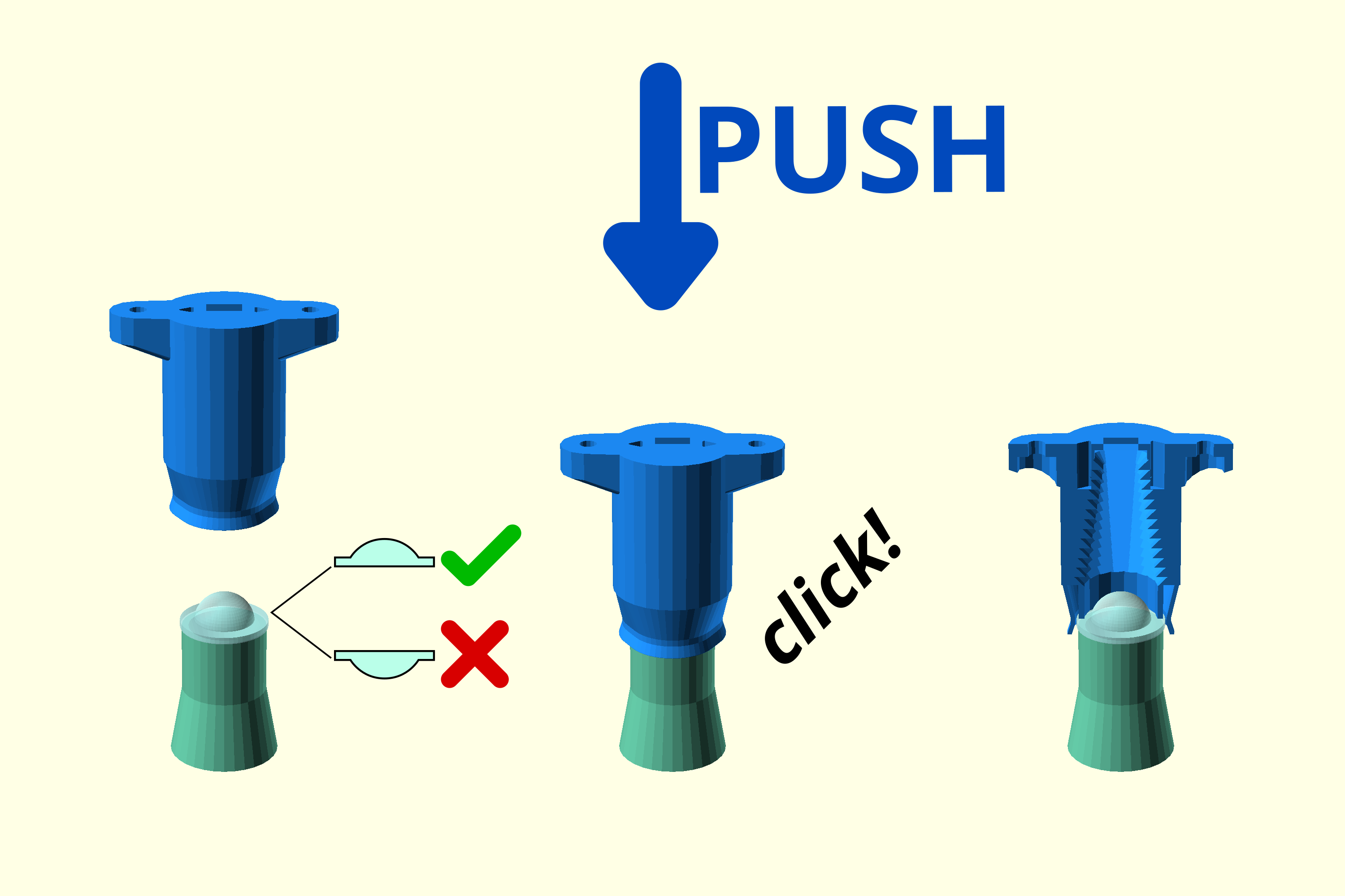
- Place the condenser lens on the lens tool flat side down
- Take the upright condenser and align the opening over the lens
- Push down until the lens clicks into place.
- Visually inspect the positioning of the lens. It should be flat, not seated at an angle. If necessary, push against the lens tool to align properly.
Step 2: Cut out the diffuser
- Take a small sheet of 0.5mm polypropylene
 .
. - Cut out a circle, approximately 14mm in diameter, using a utility knife. It is better to be slightly smaller than required, rather than slightly larger.
- Using the condenser board spacer as a guide, make two small holes for the screws that mount the illumination.
- The diffuser is shown in white in the next step.
Step 3: Mount the diffuser and LED board
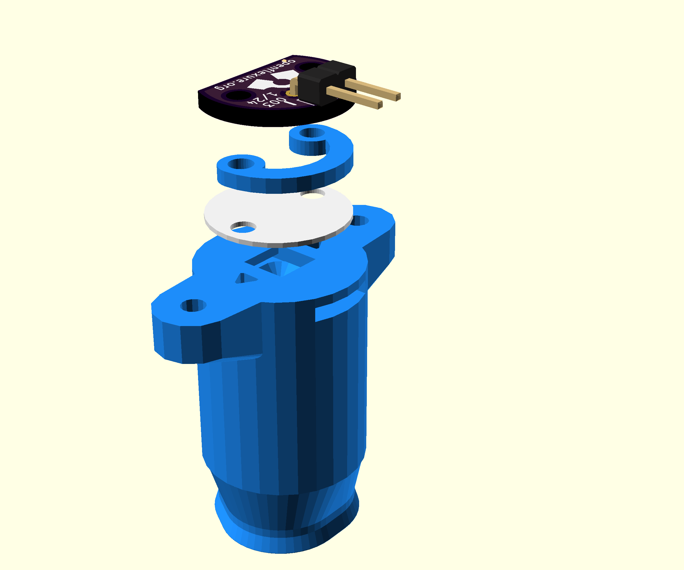
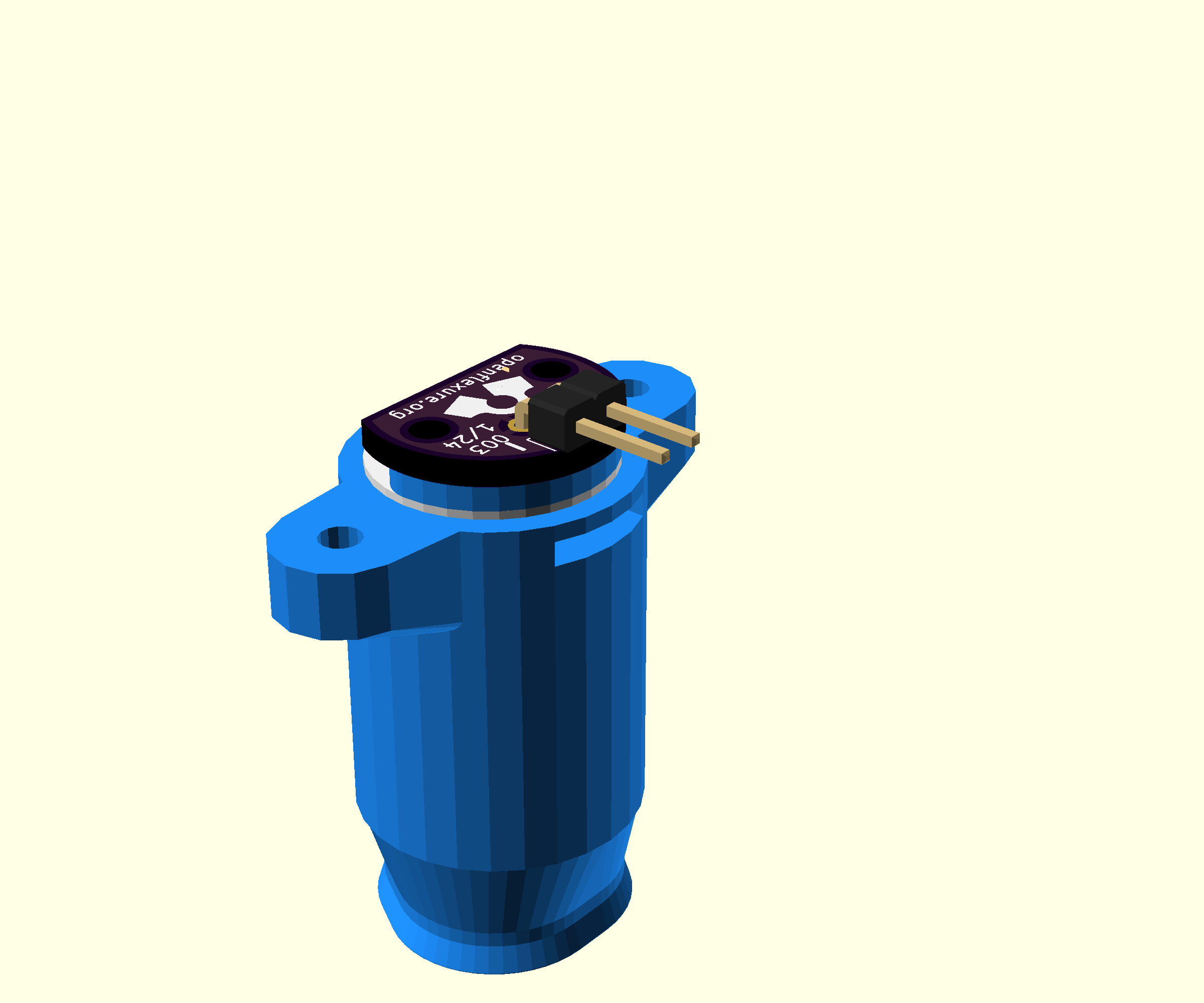
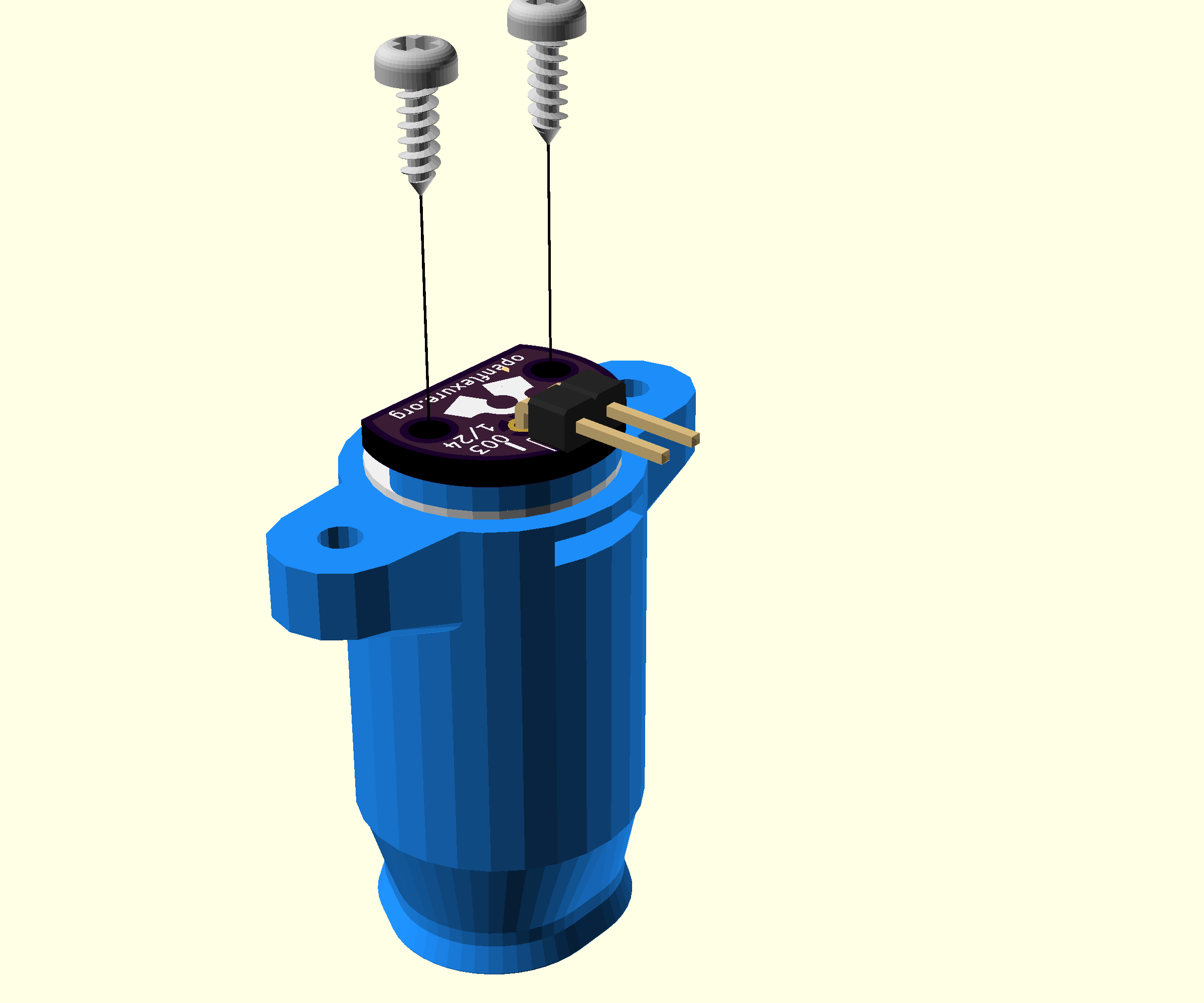
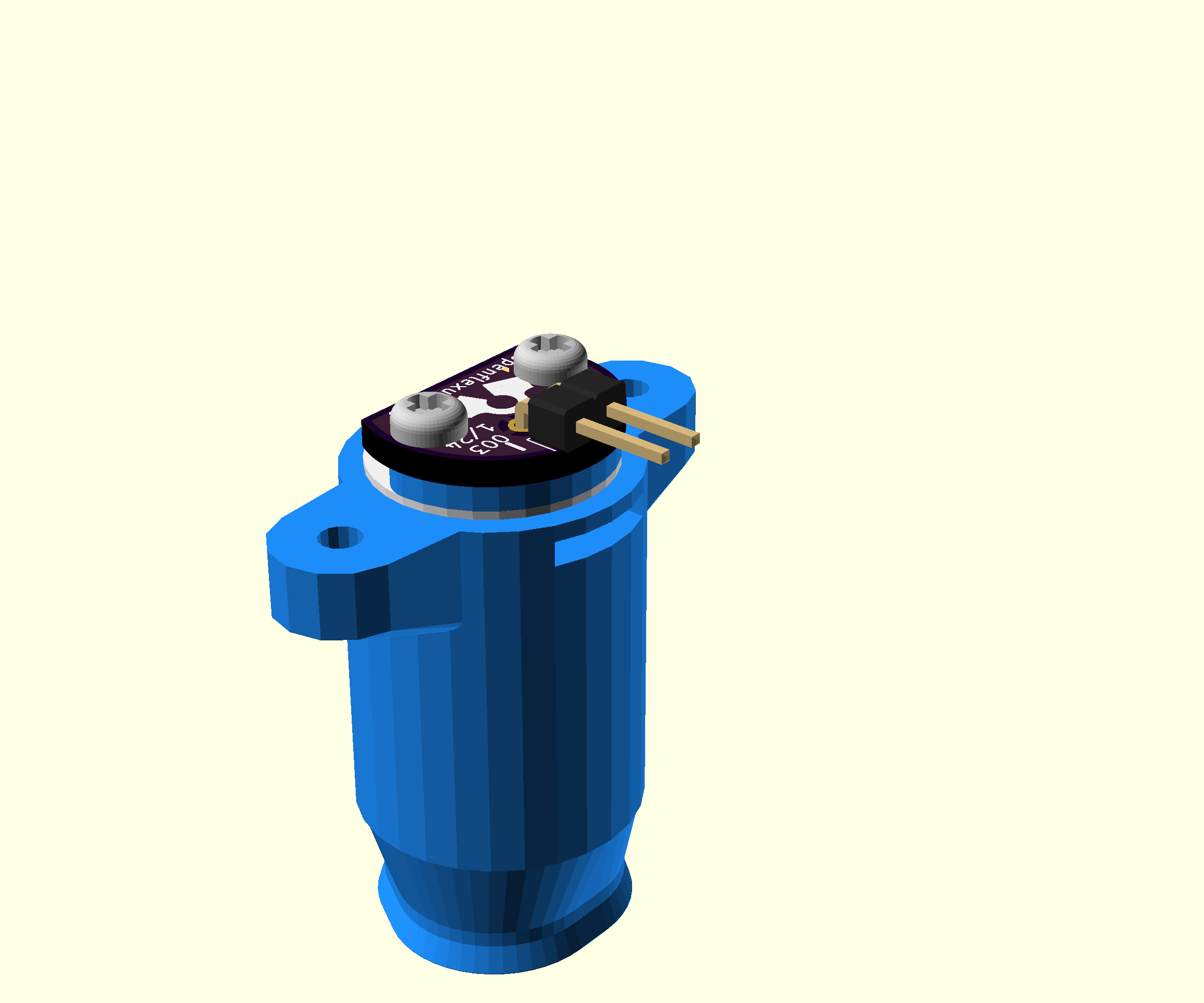

- Turn the condenser over, so the flat side is on top
- Note the position of the small slot in the side
- Place the diffuser on the condenser, then the condenser board spacer
- Place the illumination PCB with the pins towards the slot
- Fix in place with two No 2 6.5mm self tapping screws using a #1 pozidrive screwdriver
Step 4: Assemble the illumination cable
- Take a red pre-crimped female-female jumper cable (30 cm) and a black pre-crimped female-female jumper cable (30 cm).
- Attach a 2 pin Du Pont connector female housing to each end.
Step 5: Attach the illumination cable
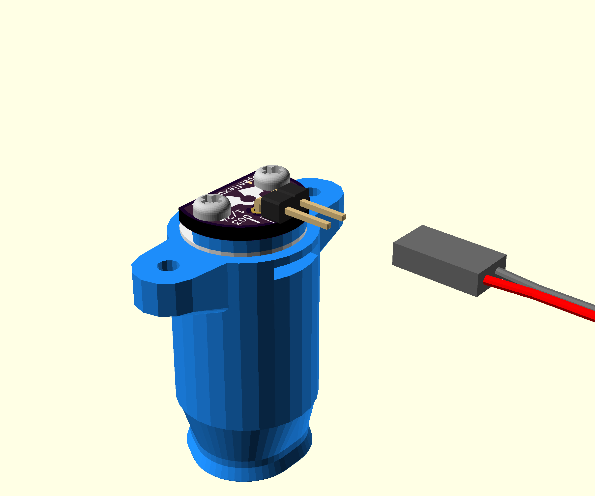
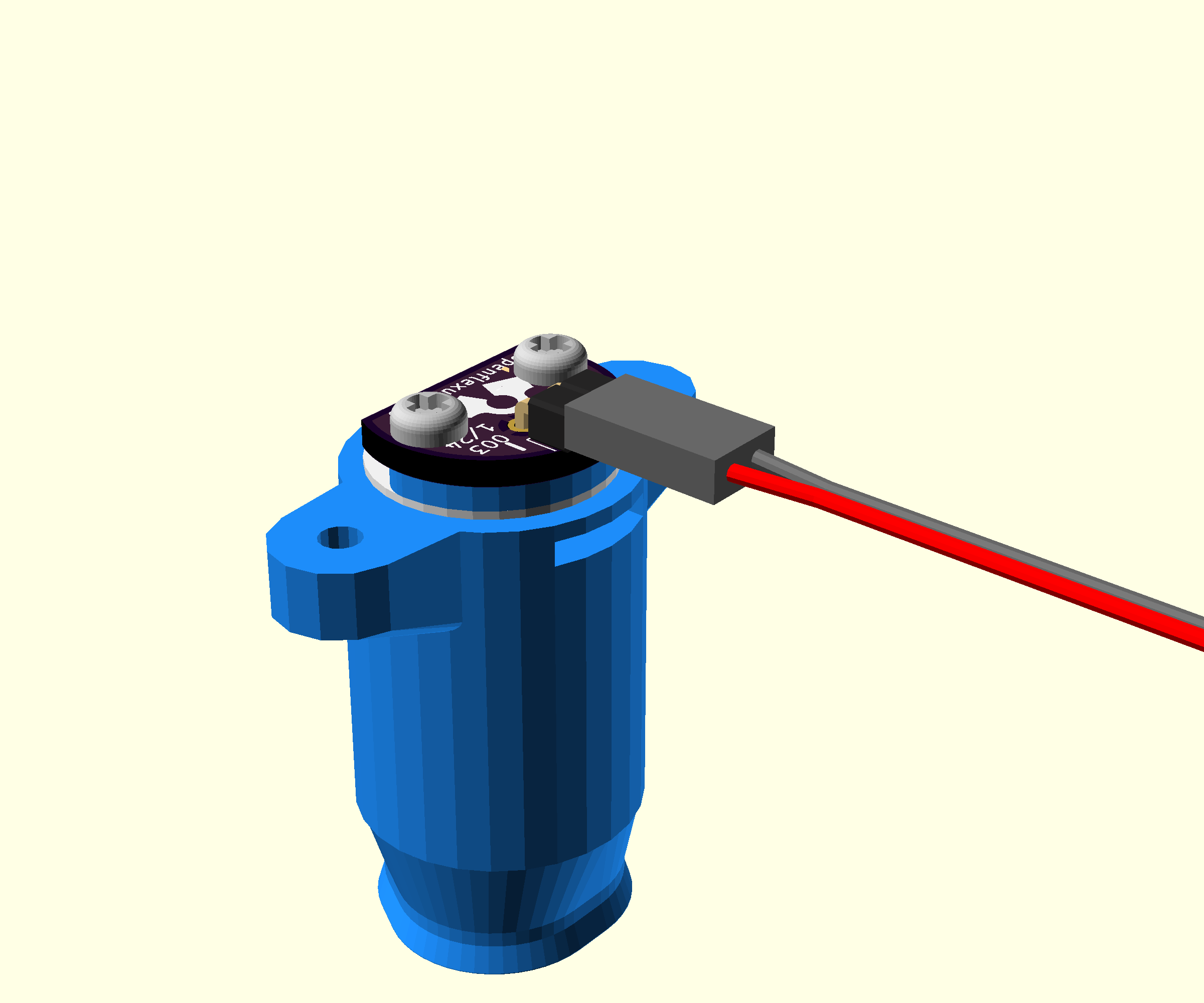

- Attach the illumination cable to the illumination PCB
- Make sure that the red wire is attached to the terminal labelled '+'
Step 6: Attach the condenser to the condenser platform
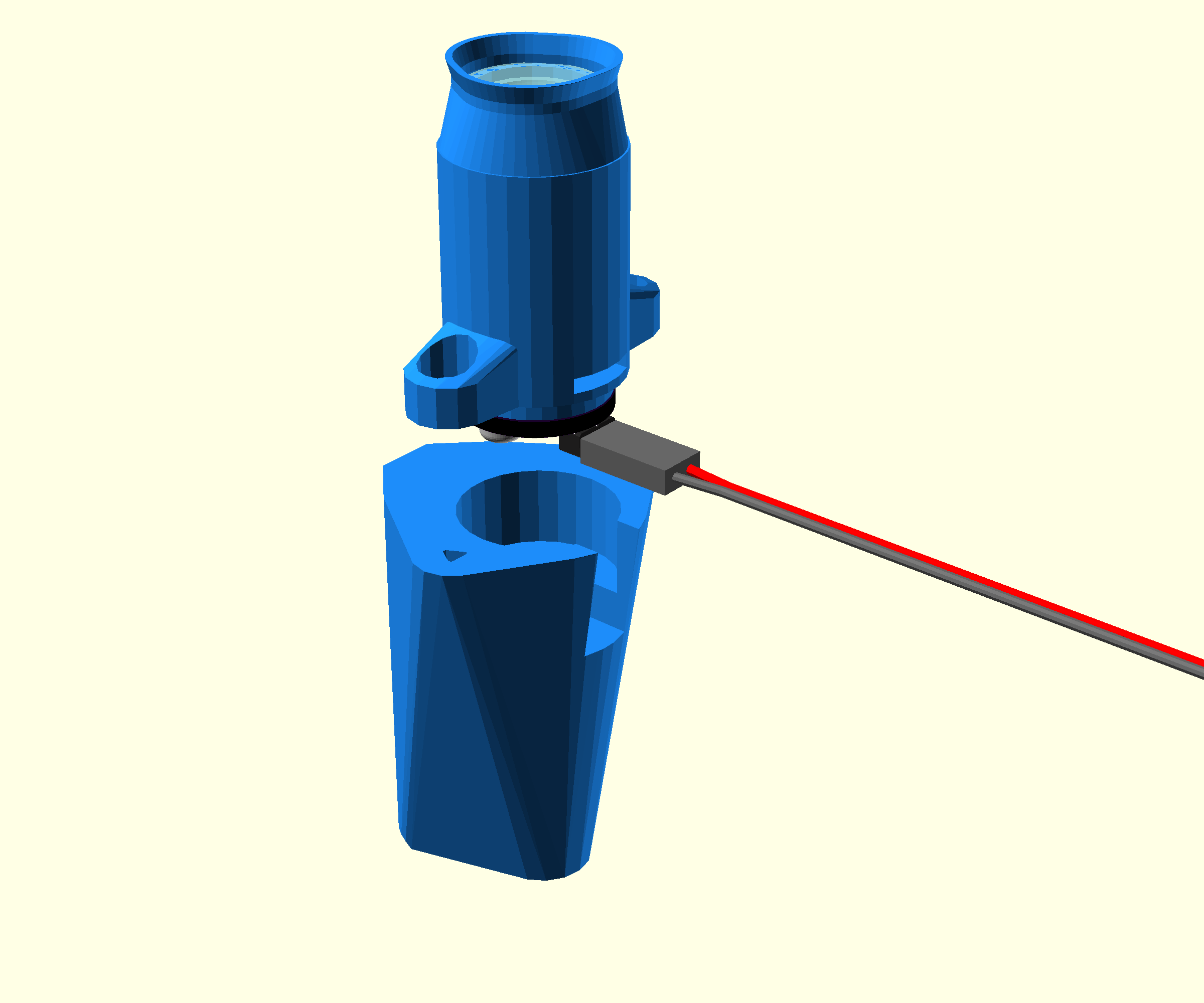
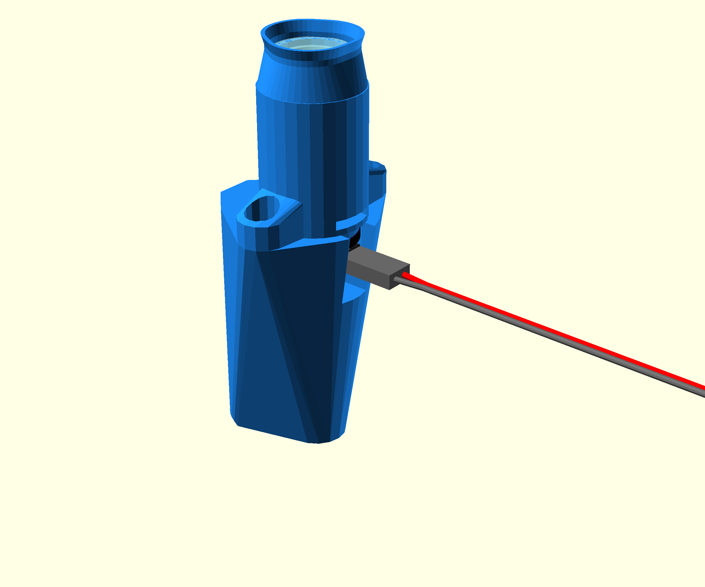
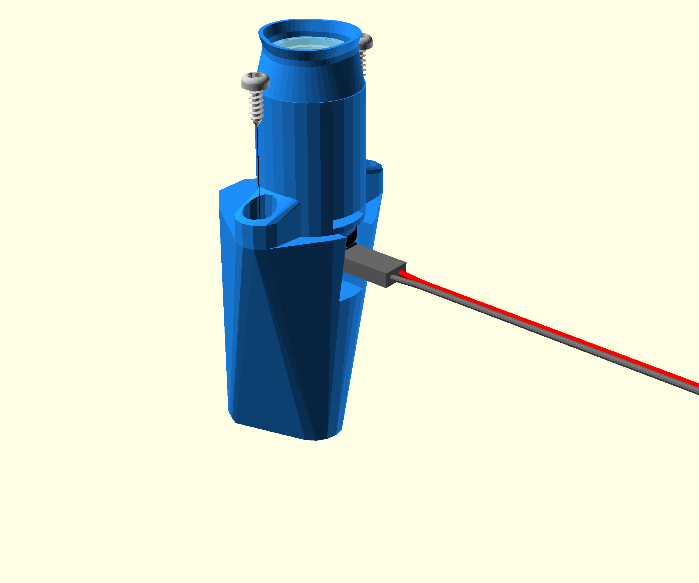
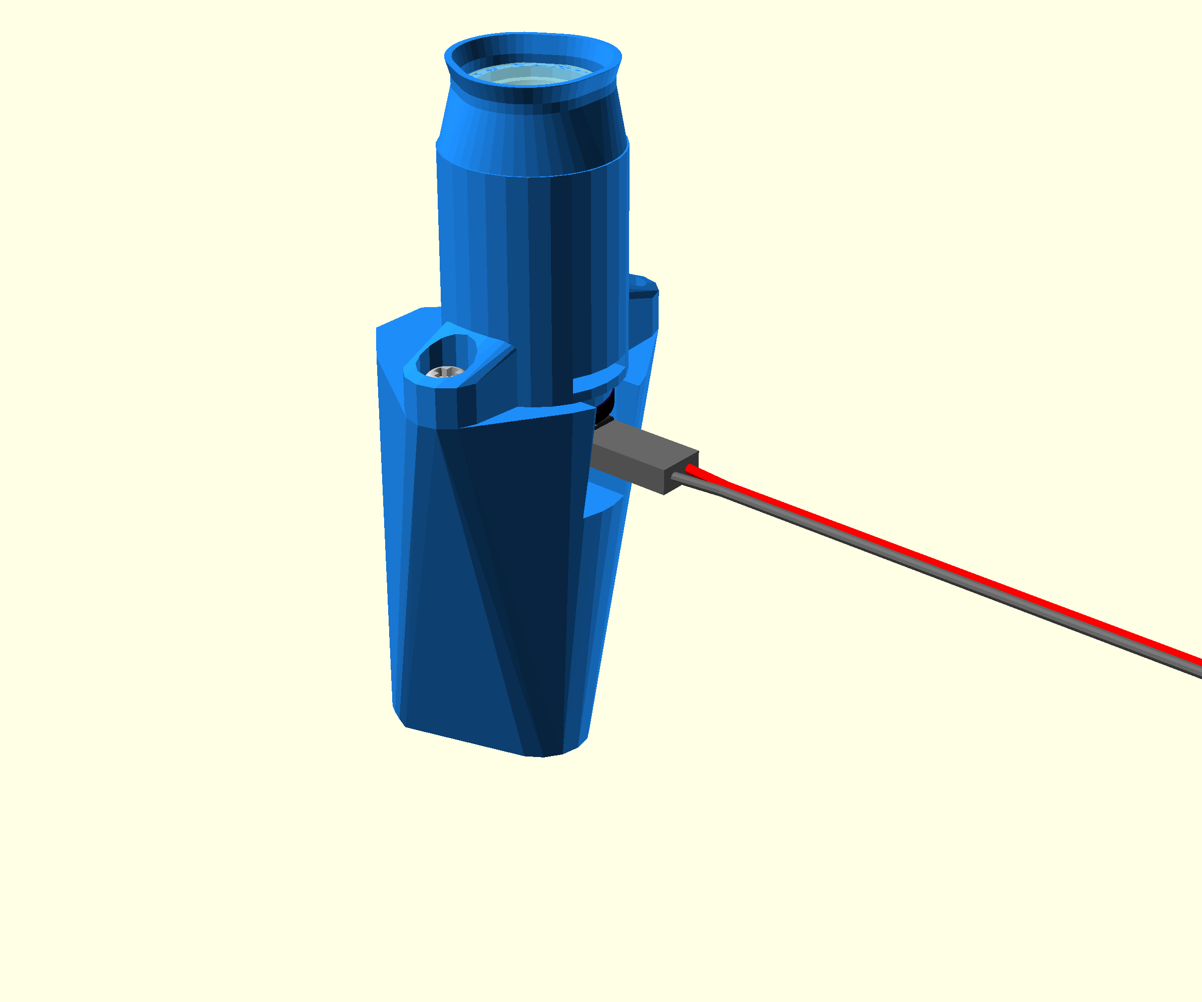

- Place the assembled condenser on the upright condenser platform.
Check that the illumination wiring and the small slot in the condenser body are both pointing away from the mounting dovetail.
- Secure in place with two No 2 6.5mm self tapping screws using a #1 pozidrive screwdriver.
Step 7: Add the condenser mounting screw
- Take an M3 nut and push it into the nut trap in the condenser platform from the top
- Take an M3x10 cap head screw and screw it into the nut, only screw a couple of turns about 5mm of thread should still be visible at this stage