
Configure and test your printer
If you have bought the plastic parts you can skip this step!
For this section you will need:
Tools
- 1 2.5mm Ball-end Allen key
- 1 extra M3x10 cap screw - For mounting trapped nuts
- 1 Fused Filament 3D printer
Materials
- 5 g of PLA filament
Mechanical Components
- 1 M3 nut
Step 1: Set your printer settings
-
All microscope parts can be printed out of PLA filament on most Fused Filament 3D printers.
-
Set your slicer to the following printer settings:
| Setting | Value |
|---|---|
| Material | PLA |
| Layer height | 0.2mm |
| Nozzle diameter | 0.4mm |
| Supports | None |
| Infill | Printer default |
| Brim | Recommended for all parts without built in brim |
| Slice gap closing radius | 0.001mm Slicer dependent - see note |
Do not print with supports.
The microscope has been designed to print without supports. Supports will damage the mechanism.
The microscope body has a custom brim included in the STL, and the condenser lens and optics module also contain small gaps. This may require you to set the slice gap closing radius.
As a general rule, strength is more important than surface finish, so very thin layers (less than 0.15mm or so) are unlikely to result in a microscope that performs any better, though it may improve the appearance.
Step 2: Test your print settings
- Now test whether your printer can print the bridges in the microscope and the custom brim on the main body, and test the assembly of nut traps
- Download the leg test and nut trap files
- Slice and print the files. Do not add brim in your slicer. This will only use about 5 grams of PLA
Step 3: Check your leg test print
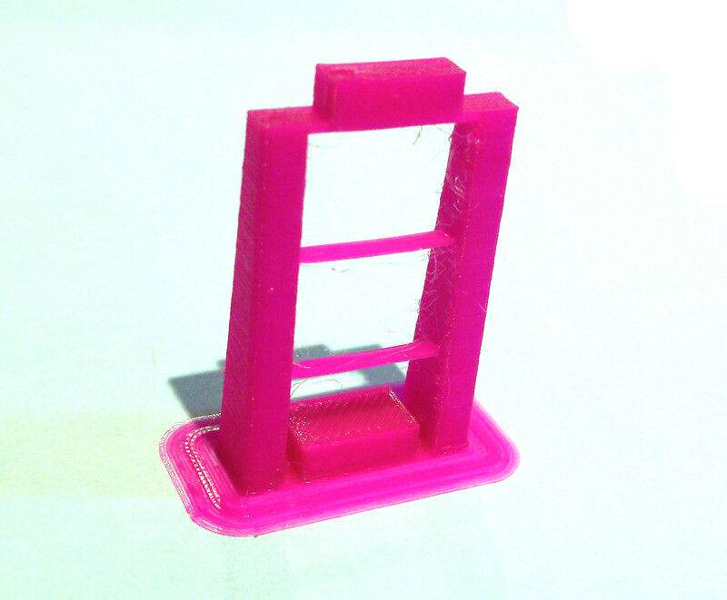
- Check that the bridge at the top of the leg test has crossed the gap cleanly
- The thinner support bridges in the middle of the legs do not need to be complete, but problems there can be an indicator of more hidden printing issues
- Check that the brim has printed as a separate object around the leg
- Check that the brim is easy to remove. If it is difficult to remove, check that it has not been joined to the leg when sliced
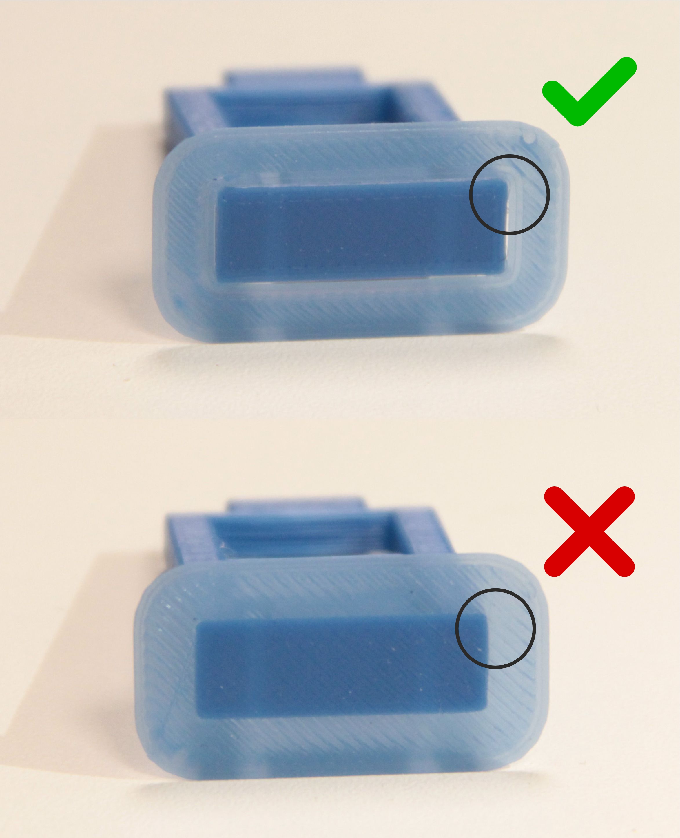
Step 4: Test assembly of the nut trap
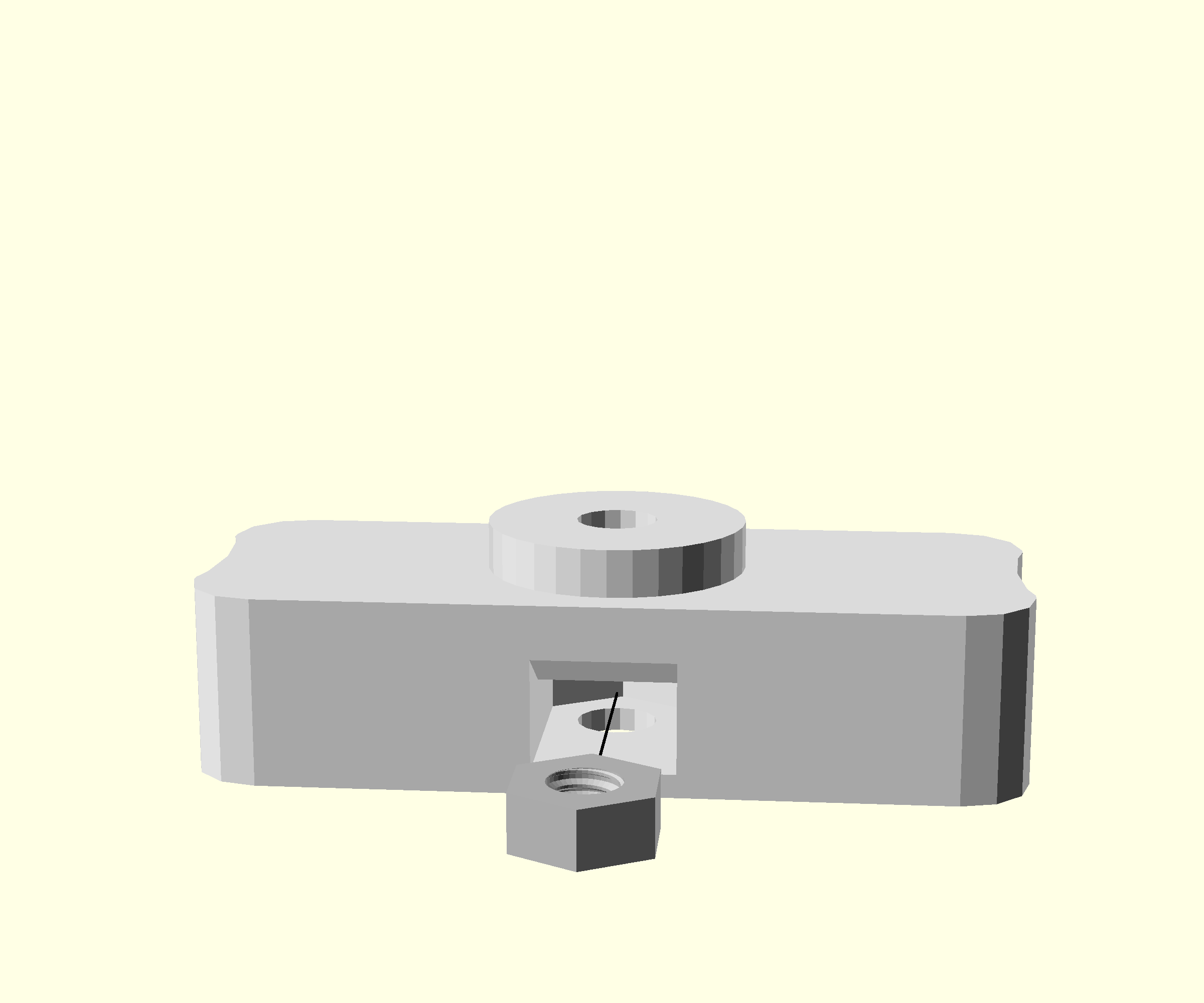
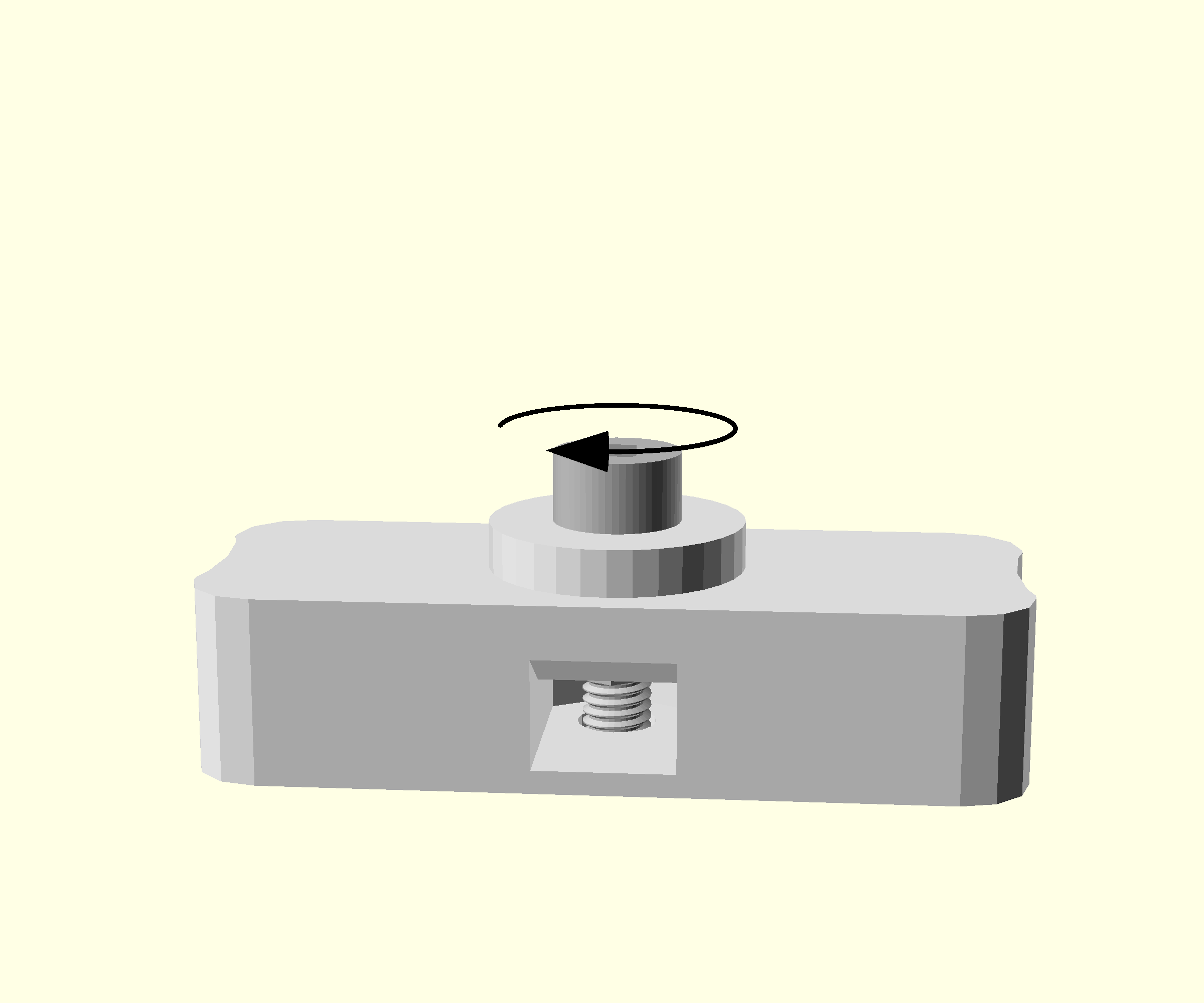
- Check that the nut hole entrance is clear and free from dangling filament. If there are obstructions this indicates that there are printing issues
- Place an M3 nut into the slot in the nut trap test object
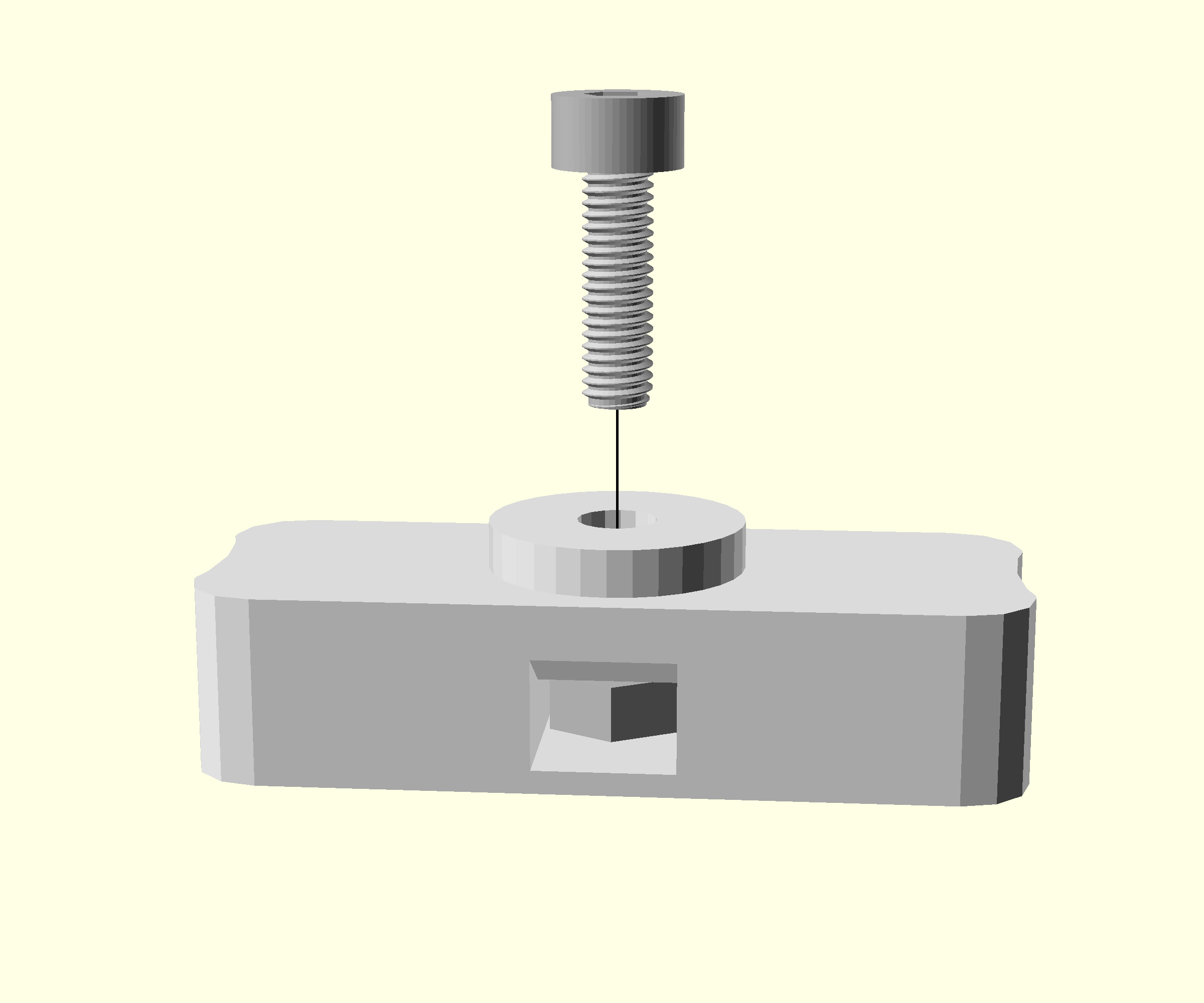
- Put an M3x10 cap head screw into the hole above the nut
- Tighten with a 2.5mm Ball-end Allen key until you feel reasonable resistance.
- Unscrew and remove the screw. The nut should stay mounted.
- Check that you have not crushed the surface of the test object with the screw. If you have, reprint the test object and try using less force to embed the nut.