
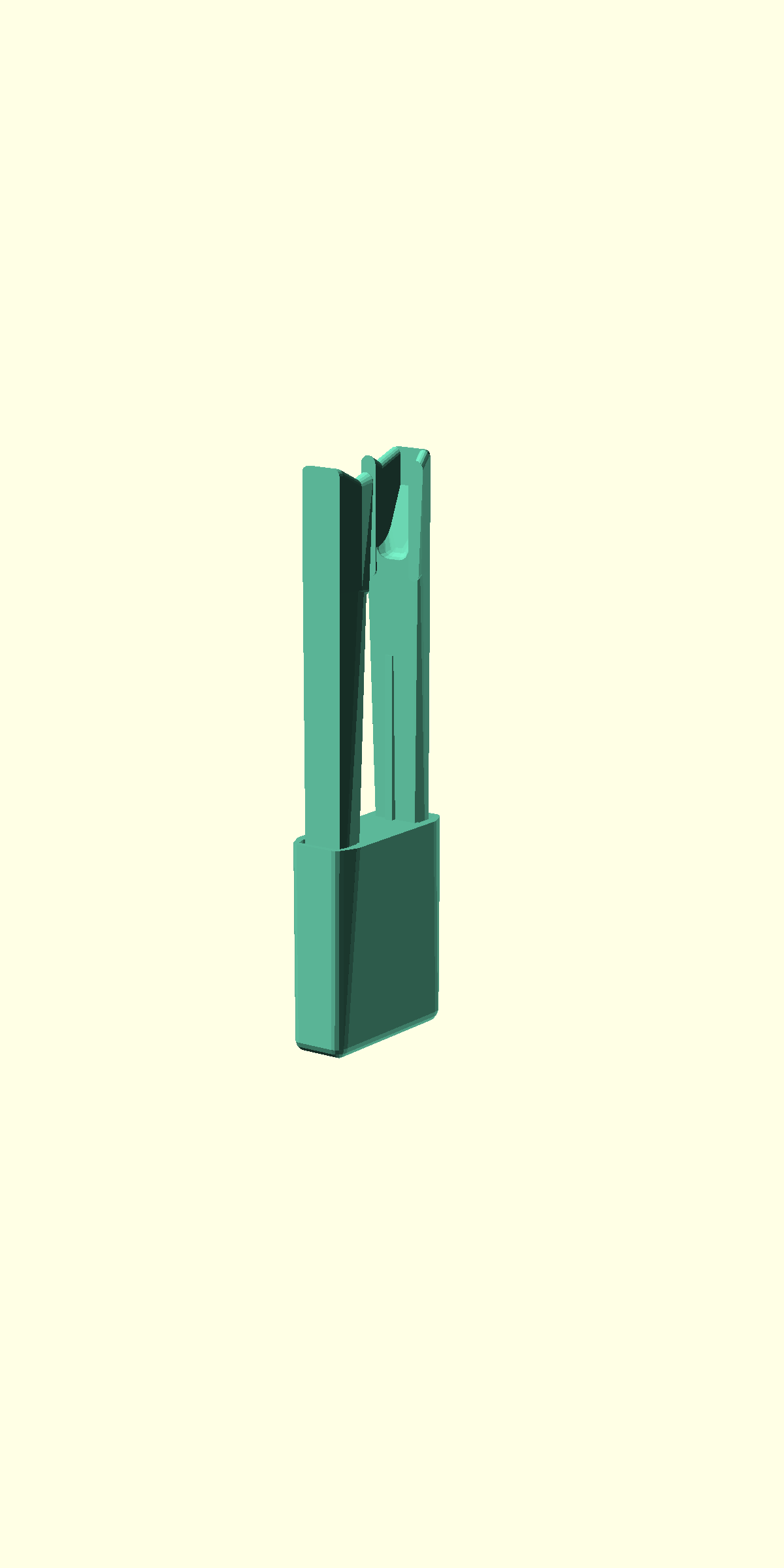
Assemble the actuators
There is one "actuator column" for each of the three axes of the OpenFlexure Microscope stage. These allow you to move the sample in X and Y, or focus the microscope by moving in Z.
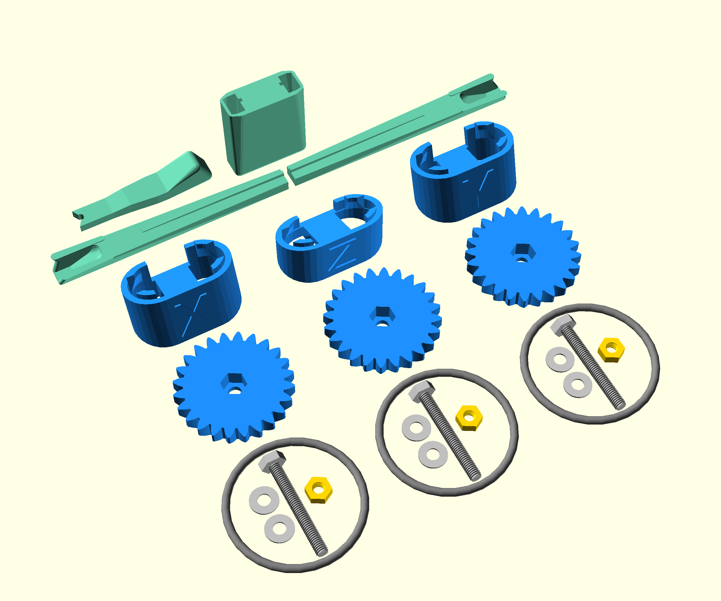
For this section you will need:
Tools
- 1 extra M3 nut - For mounting the hex bolt in the large gear
Printed Parts
- 3 feet - Each actuator has its own labelled foot
- 3 large gears
Printed Tools
- 1 band tool
- 1 band tool cover
- 1 gear holder
- 1 nut spinner
- 1 nut tool
Sub-Assemblies
Consumables
- 3 drops of light oil - Don't skip this or you will damage the screws
Mechanical Components
- 3 M3 brass nut
- 6 M3 stainless steel washers
- 3 M3x25mm stainless steel hex bolt
- 3 Viton O-ring (30mmx2mm) - "Viton band". Occasionally these break during assembly, they also need replacing periodically. Purchasing spares is recommended.
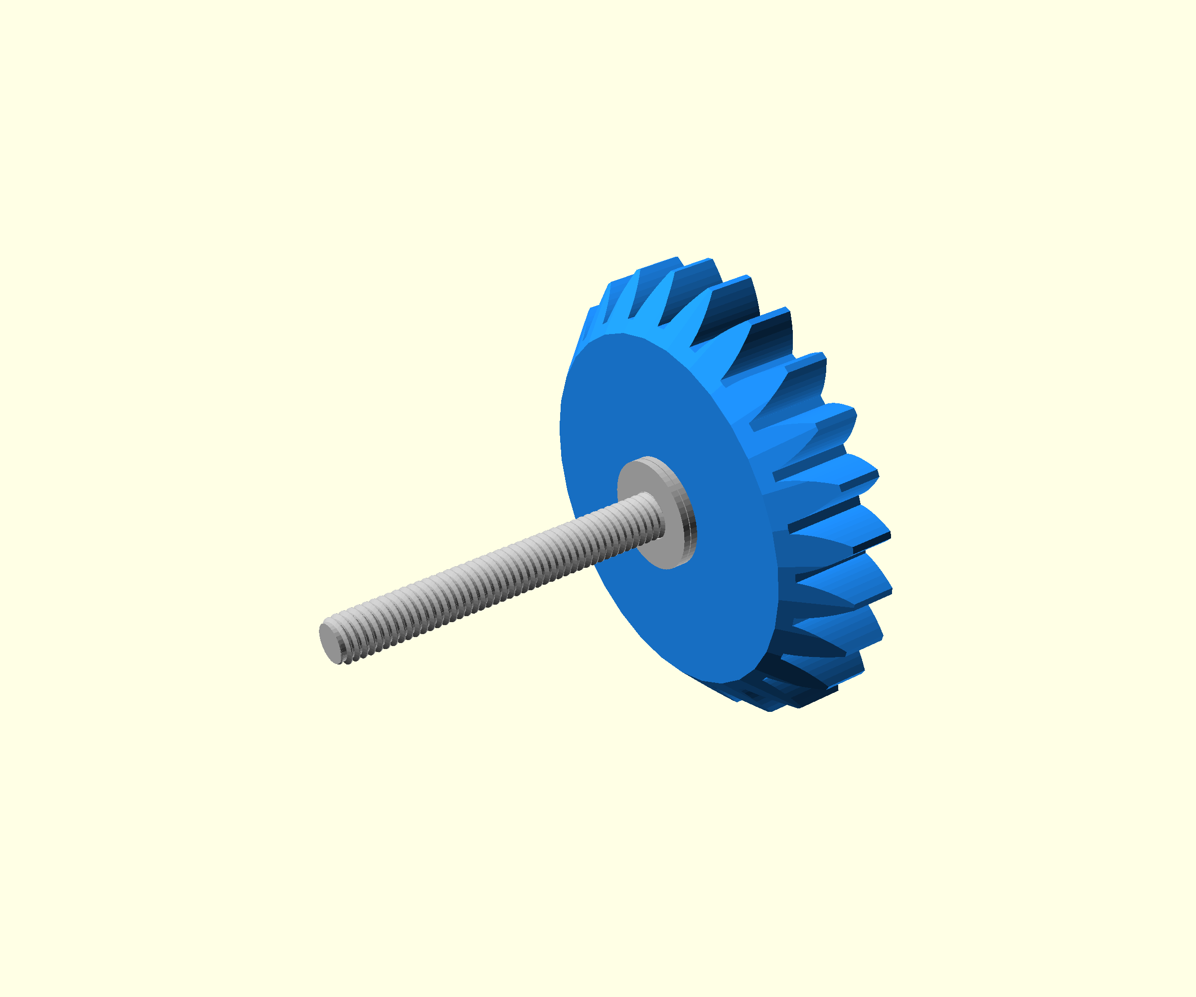
Step 1: Mount the leadscrew
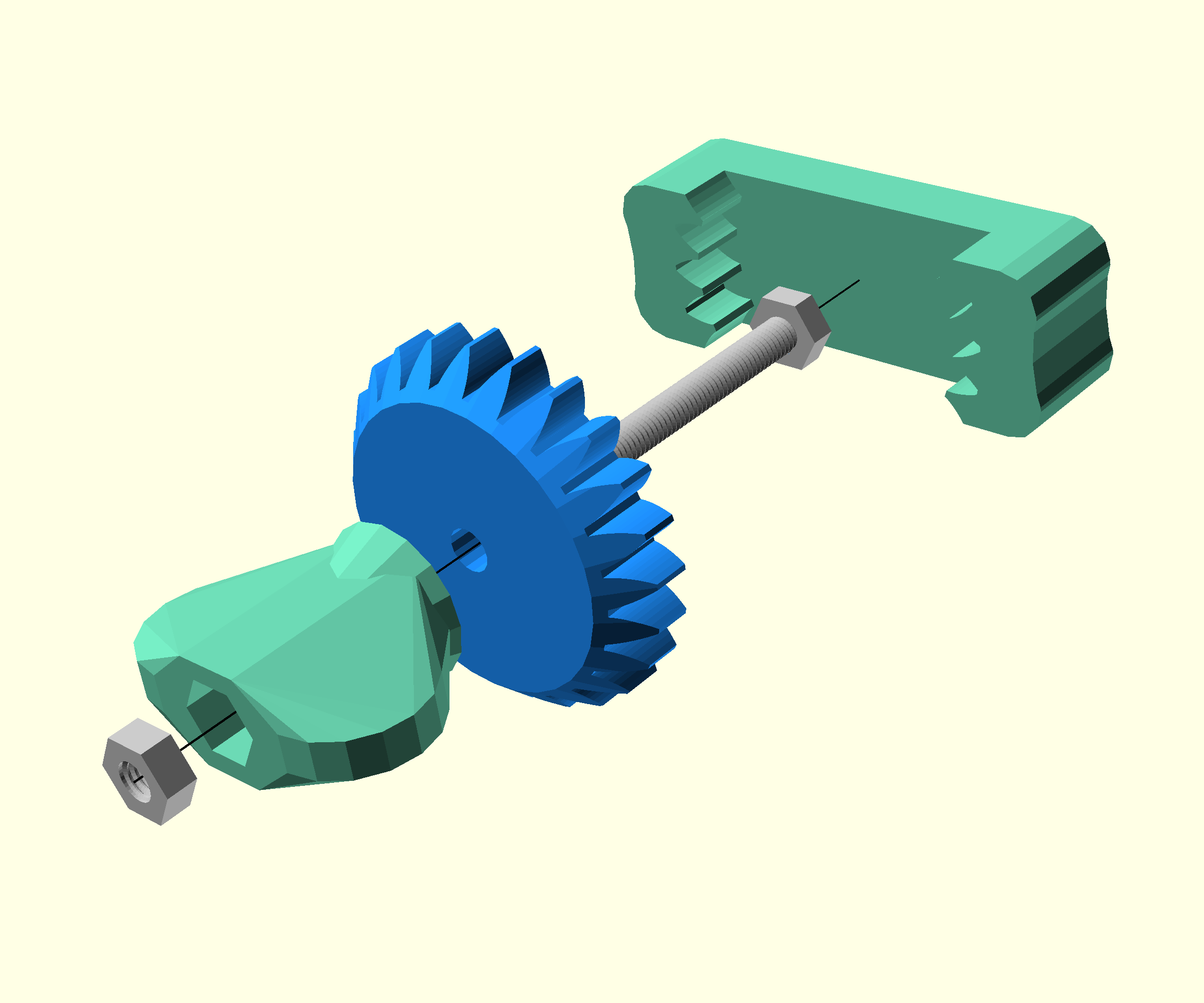
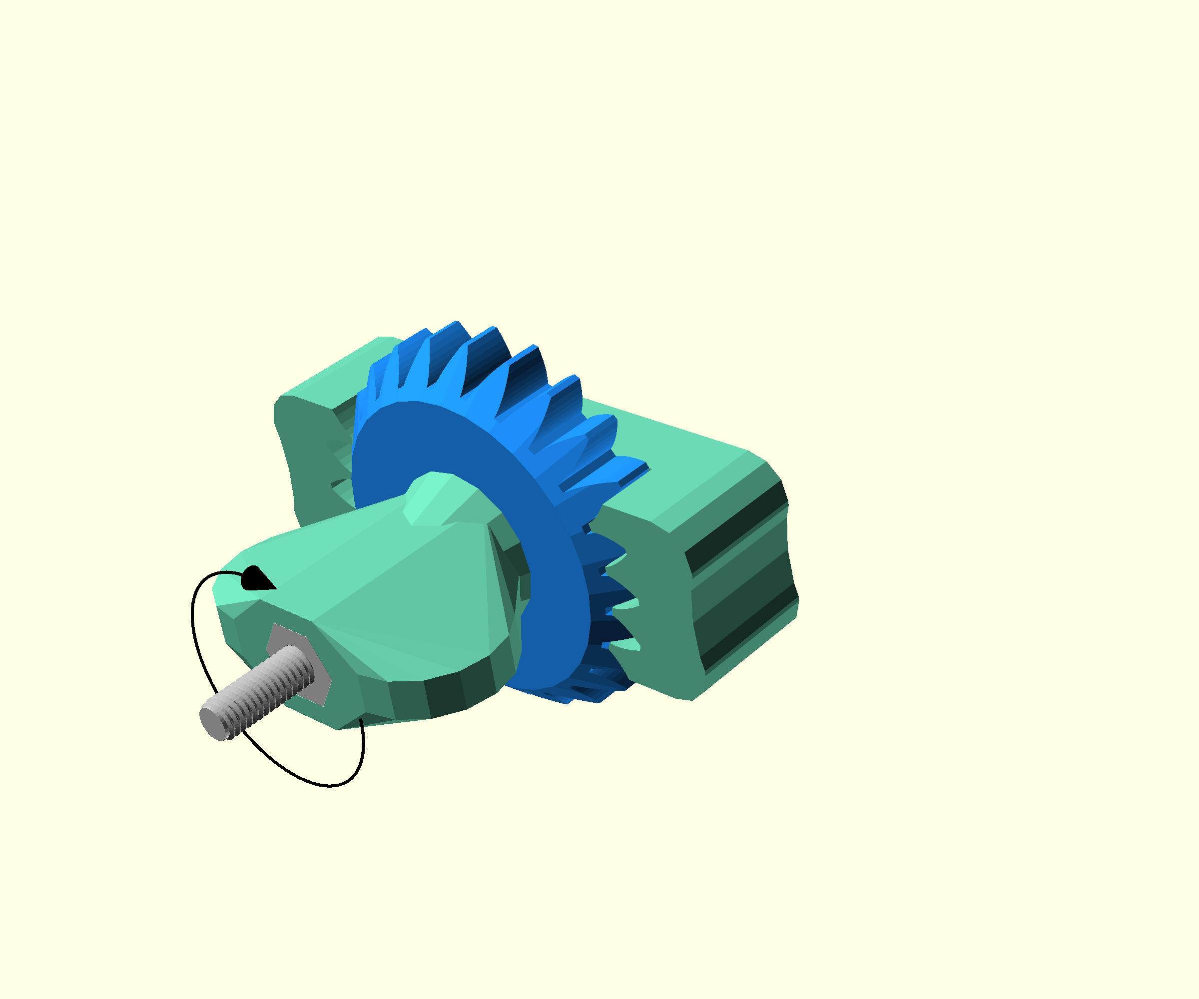
- Take one of the hex bolts
- Push it through one of the large gears, and the nut spinner
- Start to screw on a steel M3 nut, this should fit into the end of the nut spinner
- Place the gear holder over the large gear
- Tighten, by turning the gear holder and nut spinner in opposite directions. This should bed the screw into the gear
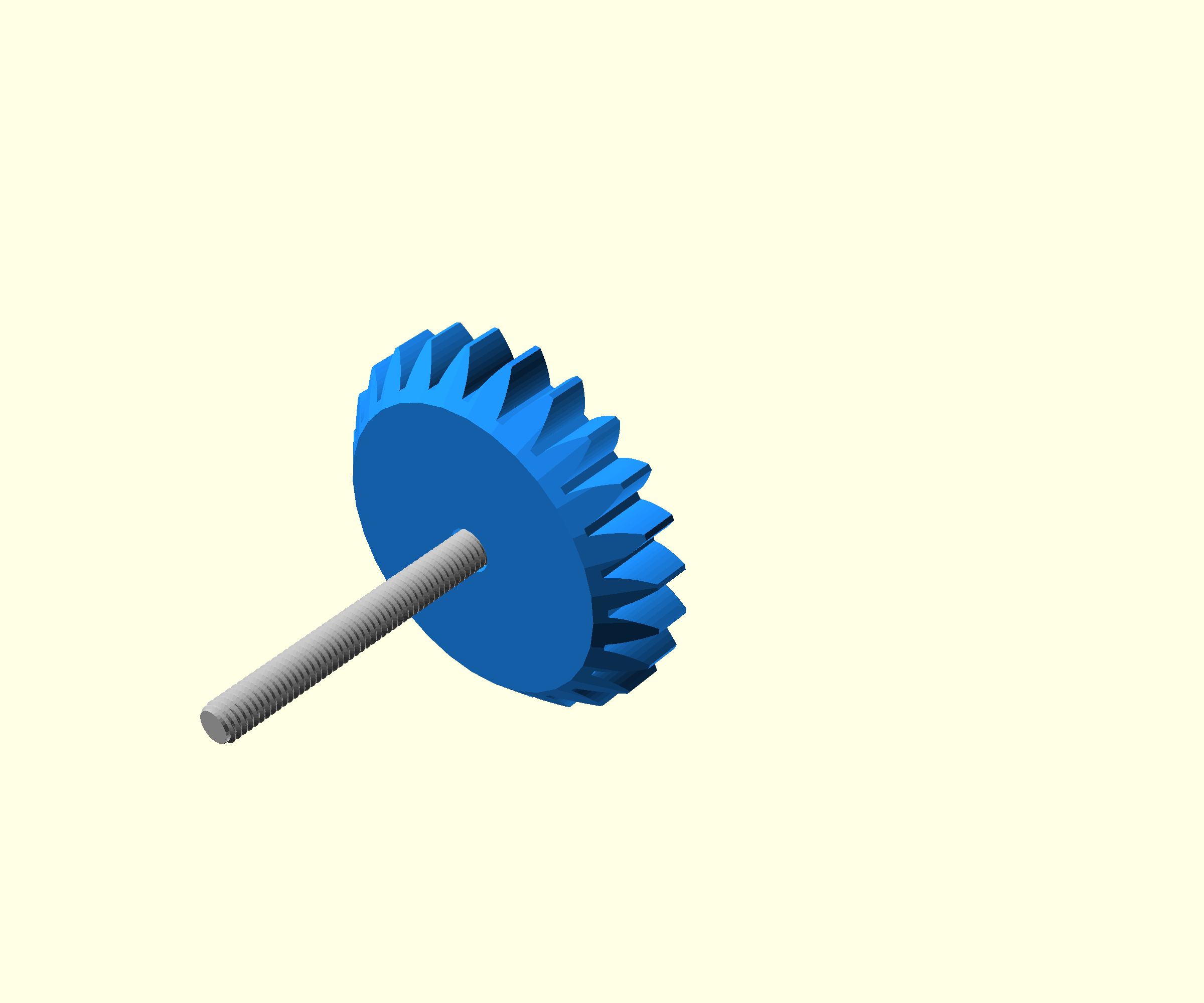
- Remove the tools by unscrewing the nut with the nut spinner. The hex bolt should now be mounted in the gear
Step 2: Insert the nut
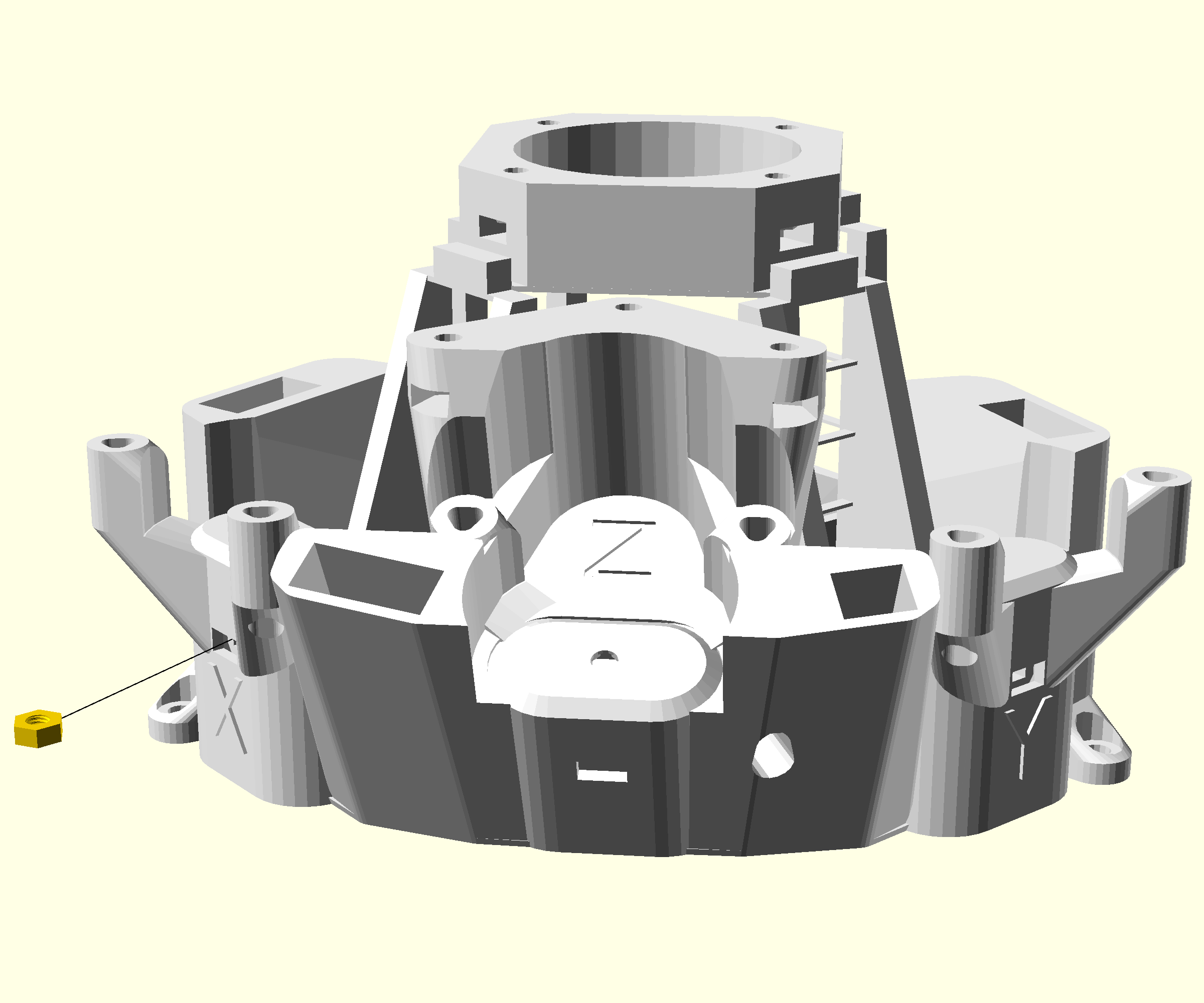
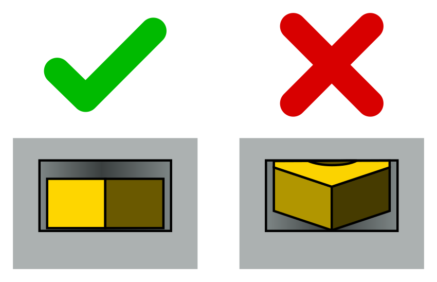
- Insert a brass nut into the x actuator through the hole in the front of the main body
- Looking through the hole you should see the side of the nut. If it is tilted so you can see the top, tap the microscope until it sits flat
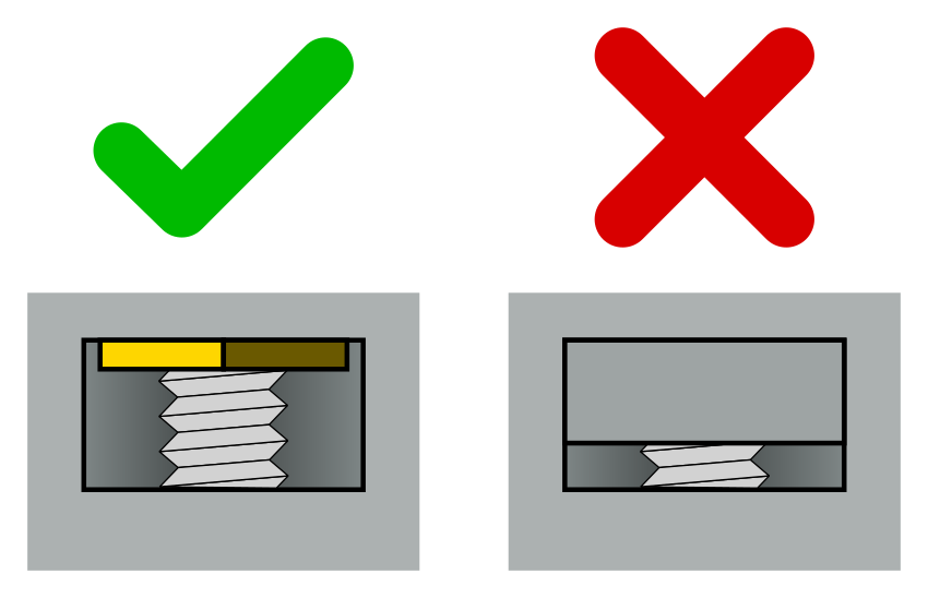
Step 3: Add washers and oil the lead screw
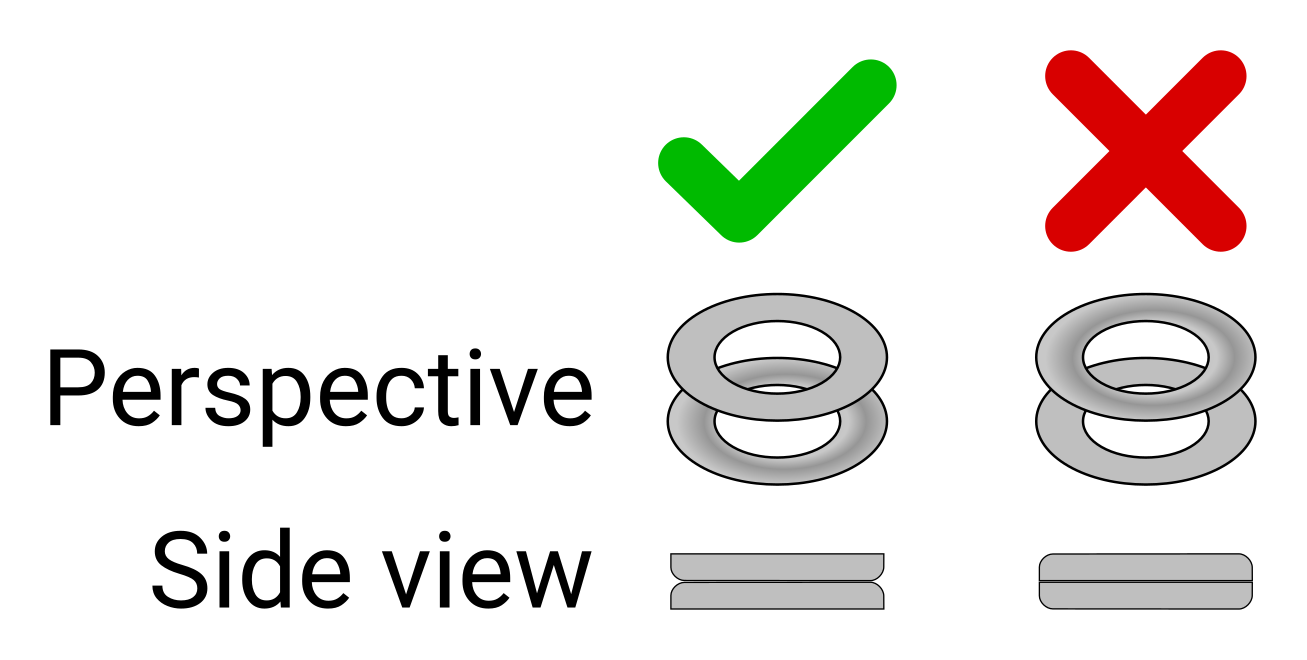
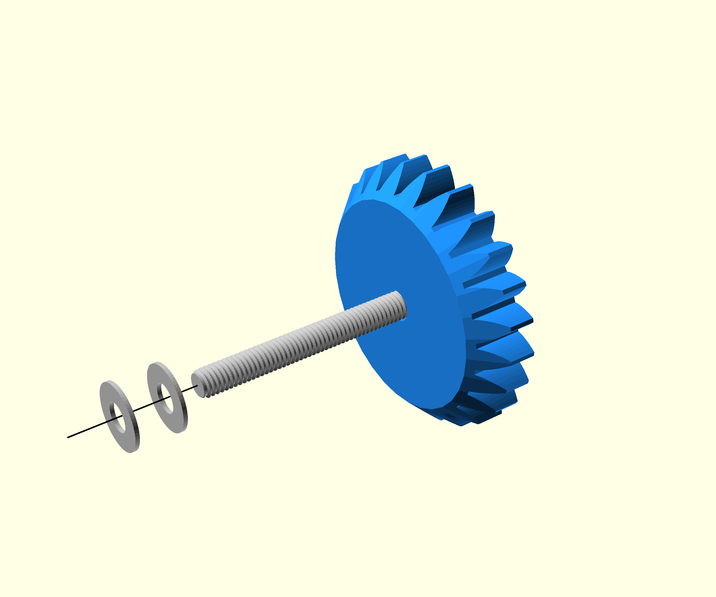
- Line up two washers so that the slightly curved sides are facing each other
- Take the gear with the hex bolt mounted into it, and slip the two washers onto the thread
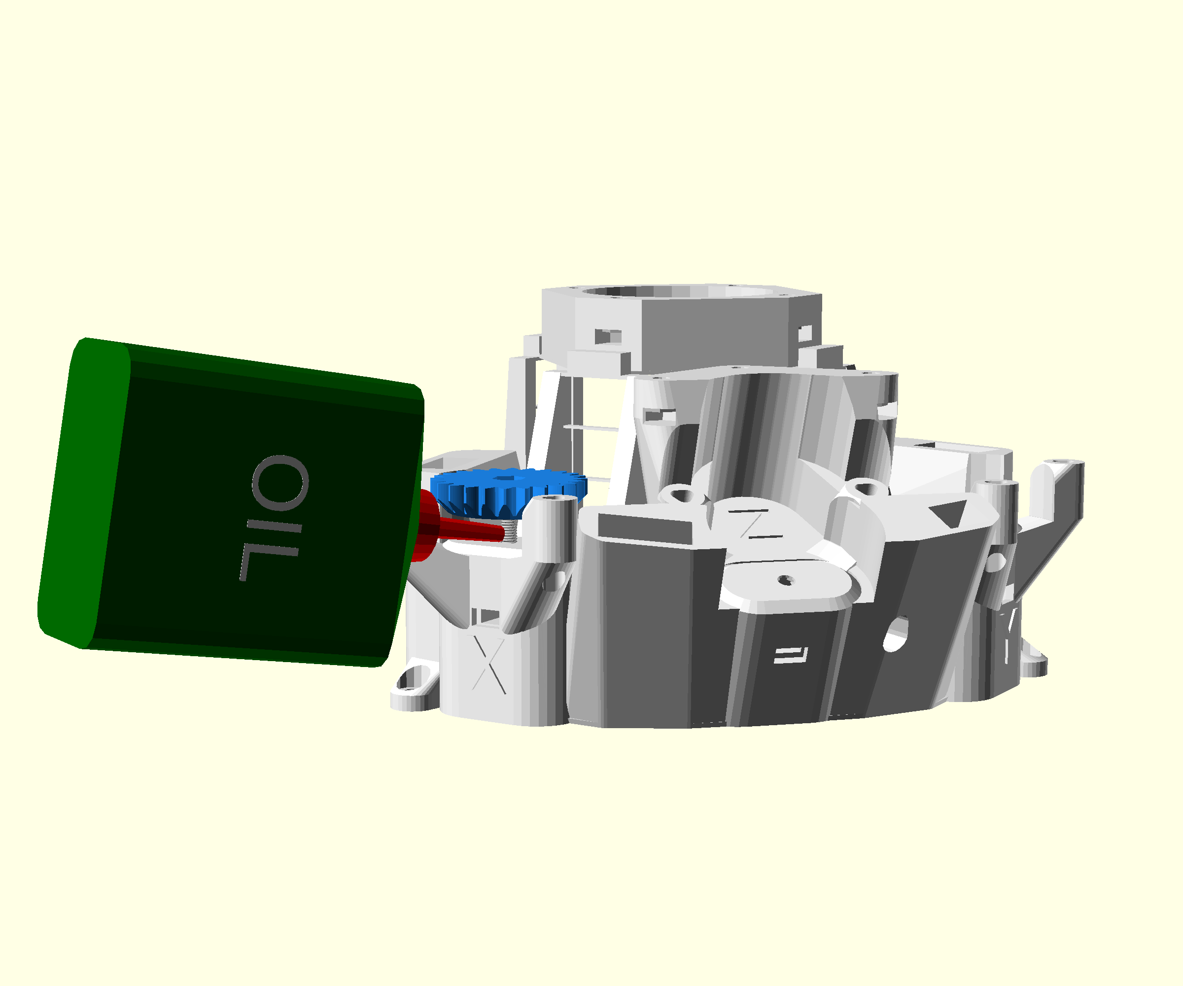
- Lightly squeeze the oil bottle so that one drip starts to form but doesn't fall
- Touch the drip to the screw so that the oil starts to coat the thread
- Lift the nozzle from the thread and remove excess oil from the nozzle
- Without squeezing the oil bottle, gently run the nozzle up and down the thread to spread the oil evenly over the thread
- The oil should be barely visible in the screw threads.
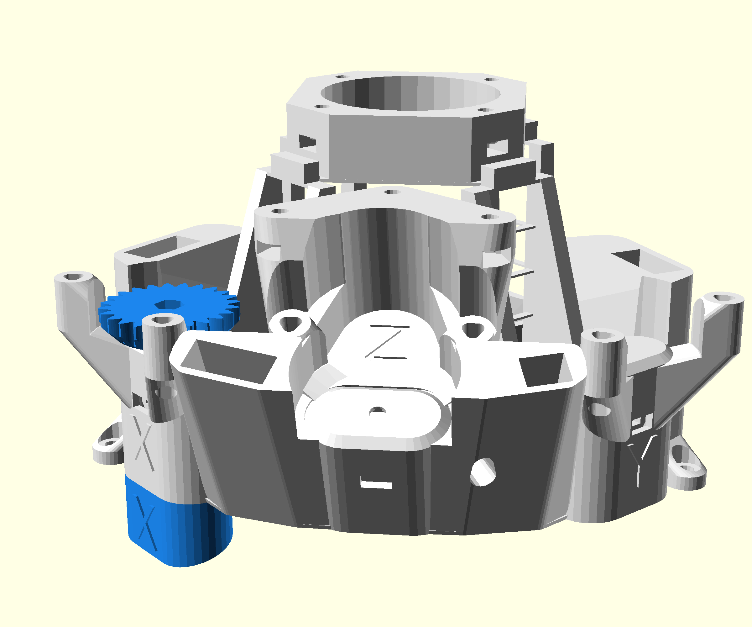
Step 4: Attach the gear
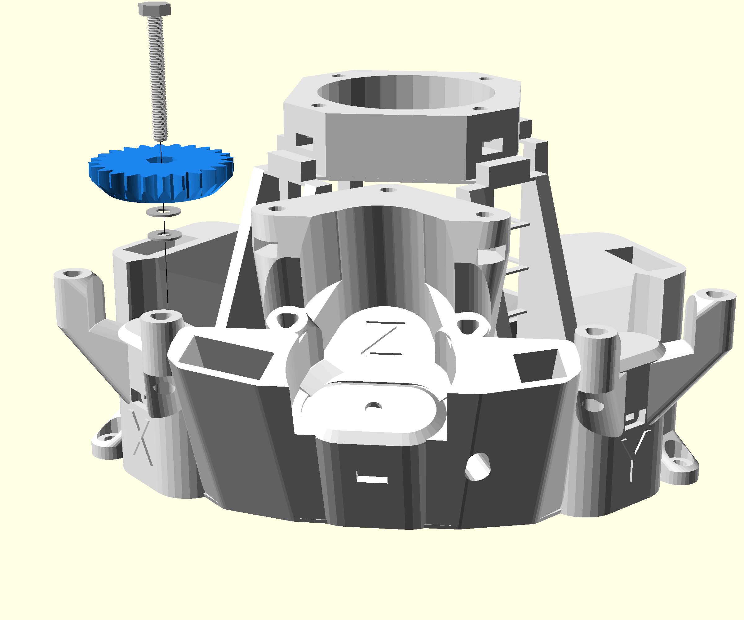
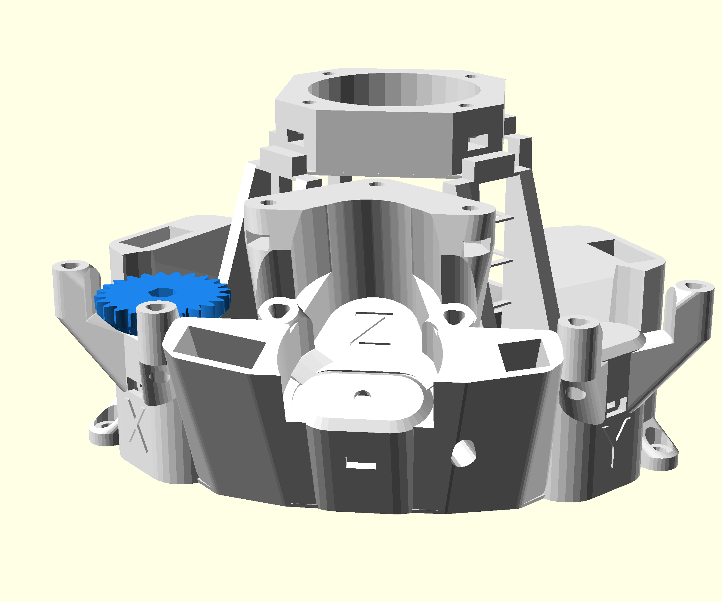
- Take the oiled bolt with two washers and push the bolt through the hole at the top of the x actuator until it reaches the nut
- Screw the bolt into the nut until the nut is completely lifted up. (If the nut turns, hold it in place with the nut tool)
Step 5: Assemble the band insertion tool

- Insert the two arms of the band tool into the band tool cover
Step 6: Prepare the actuator
- Look through the hole you inserted the nut into
- You should be able to see the screw thread of the hex bolt
- Rotate the gear until the screw is clearly visible through this hole
- Push the nut tool into the hole to hold the internal actuator in place
Step 7: Attach the viton bands and foot
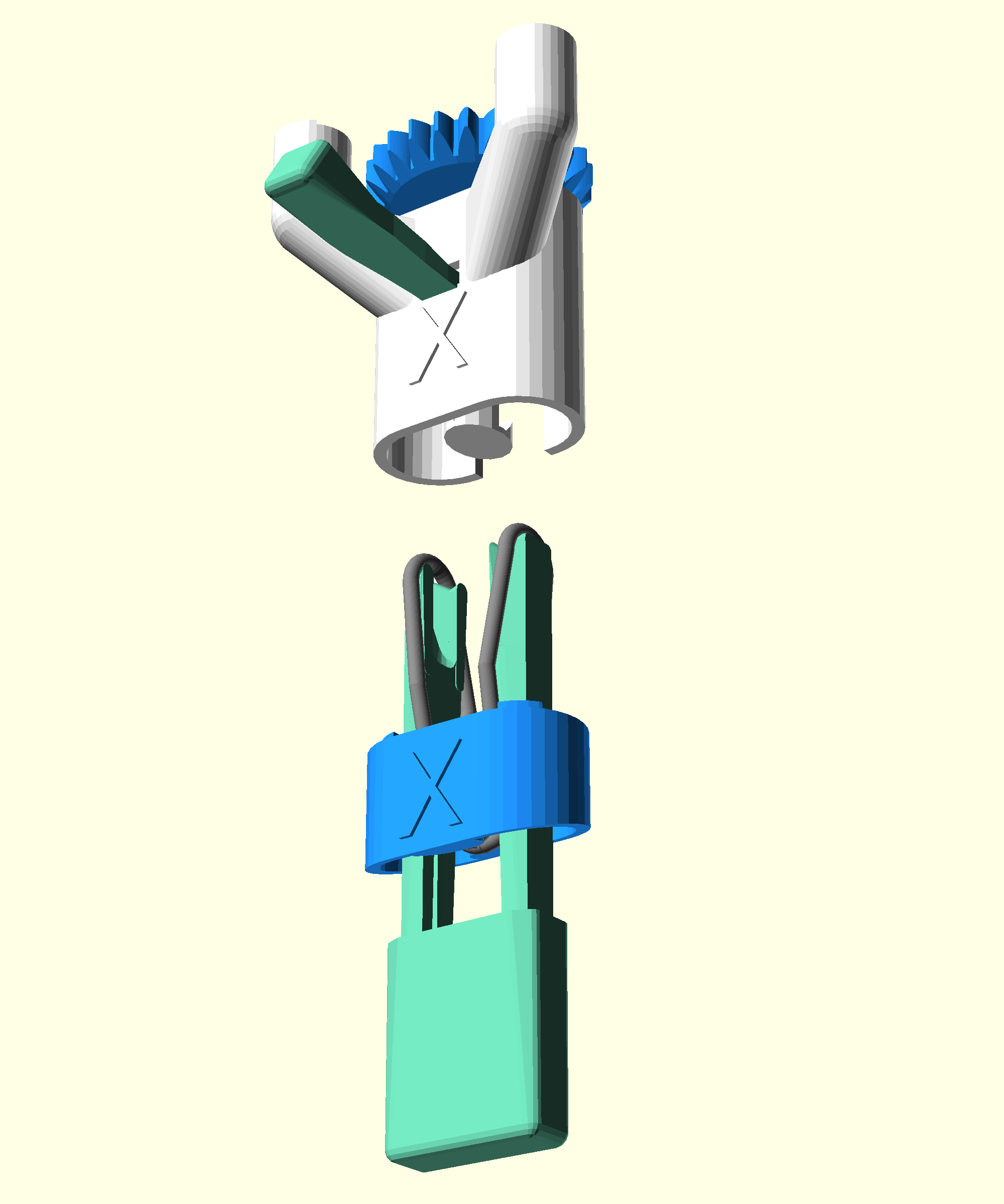
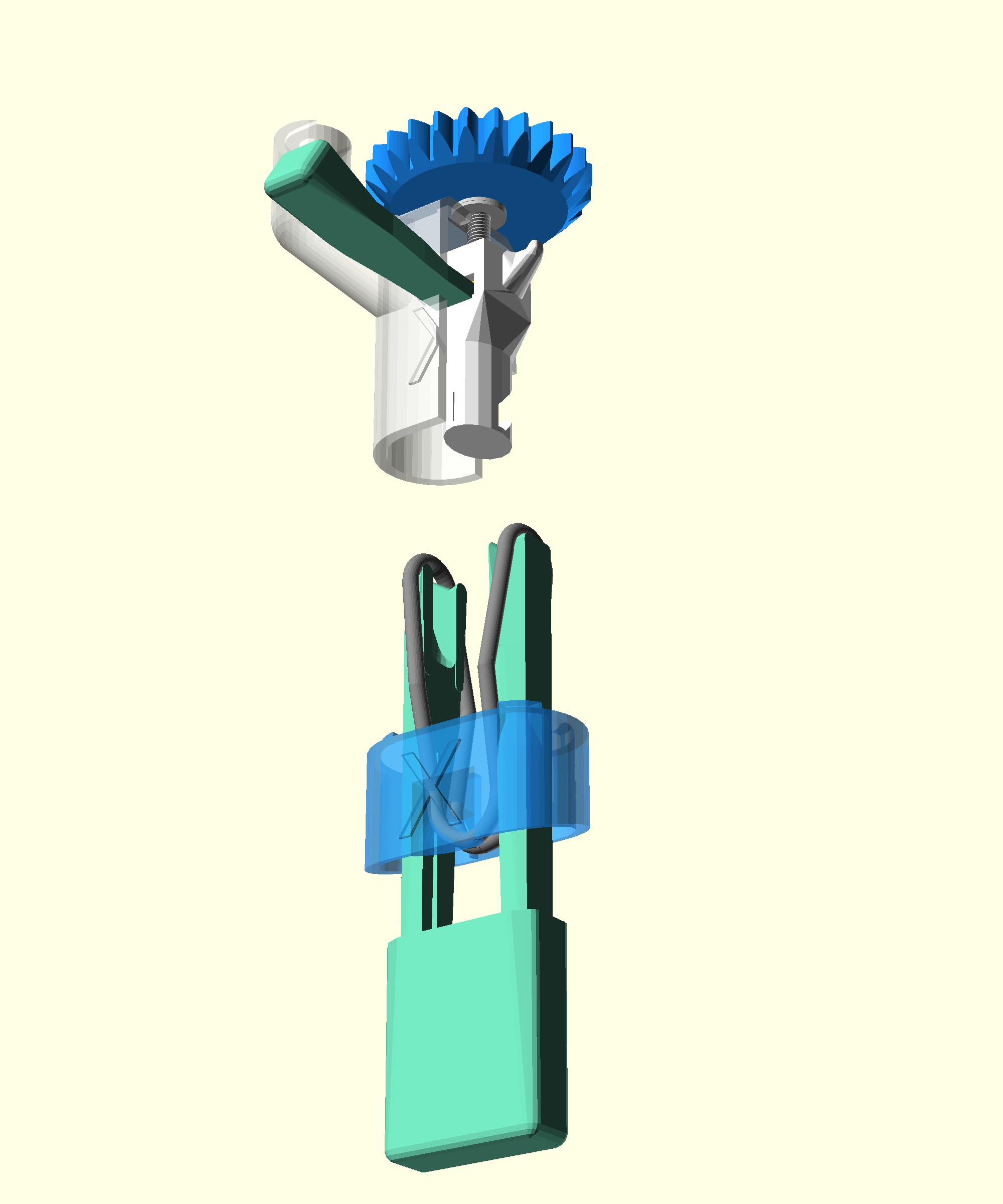
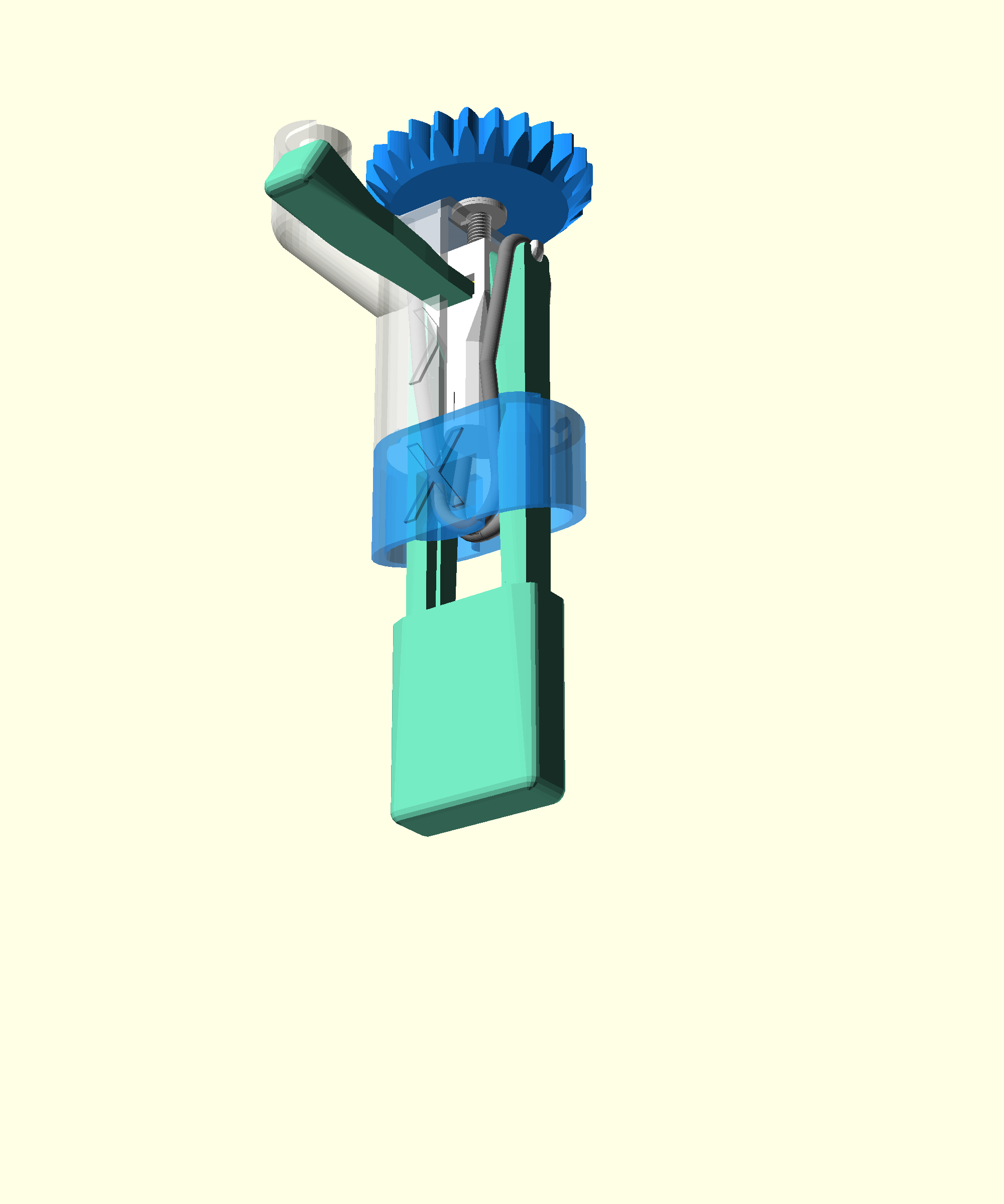
This is the trickiest part of the microscope build. In this step you will clip bands onto hooks inside each actuator.
- Take the foot for the x actuator
- Loop a viton band through the foot
- Push the assembled band tool through the foot and hook the band onto the tool on each side
- Check that the band sits in the groove under the foot, and is pulled evenly on both sides of the band tool
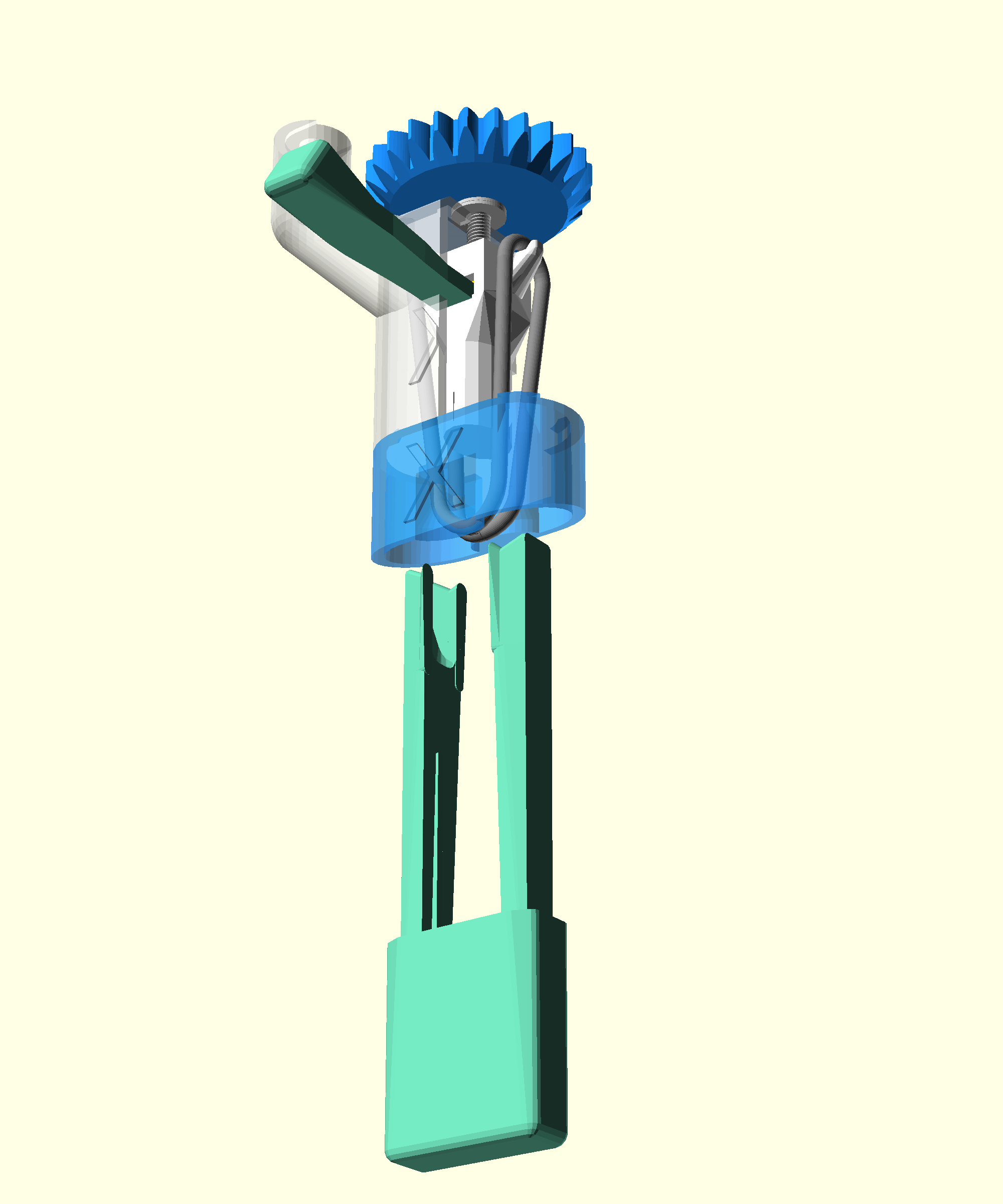
- Align the foot under the microscope so that the letter faces outwards
- Place the foot onto the actuator
- Check that the nut tool is still blocking the actuator column
- Push the band tool into the microscope until the band clicks into place. This requires some force
- Remove the band tool
If you had problems with this step, see the troubleshooting page.
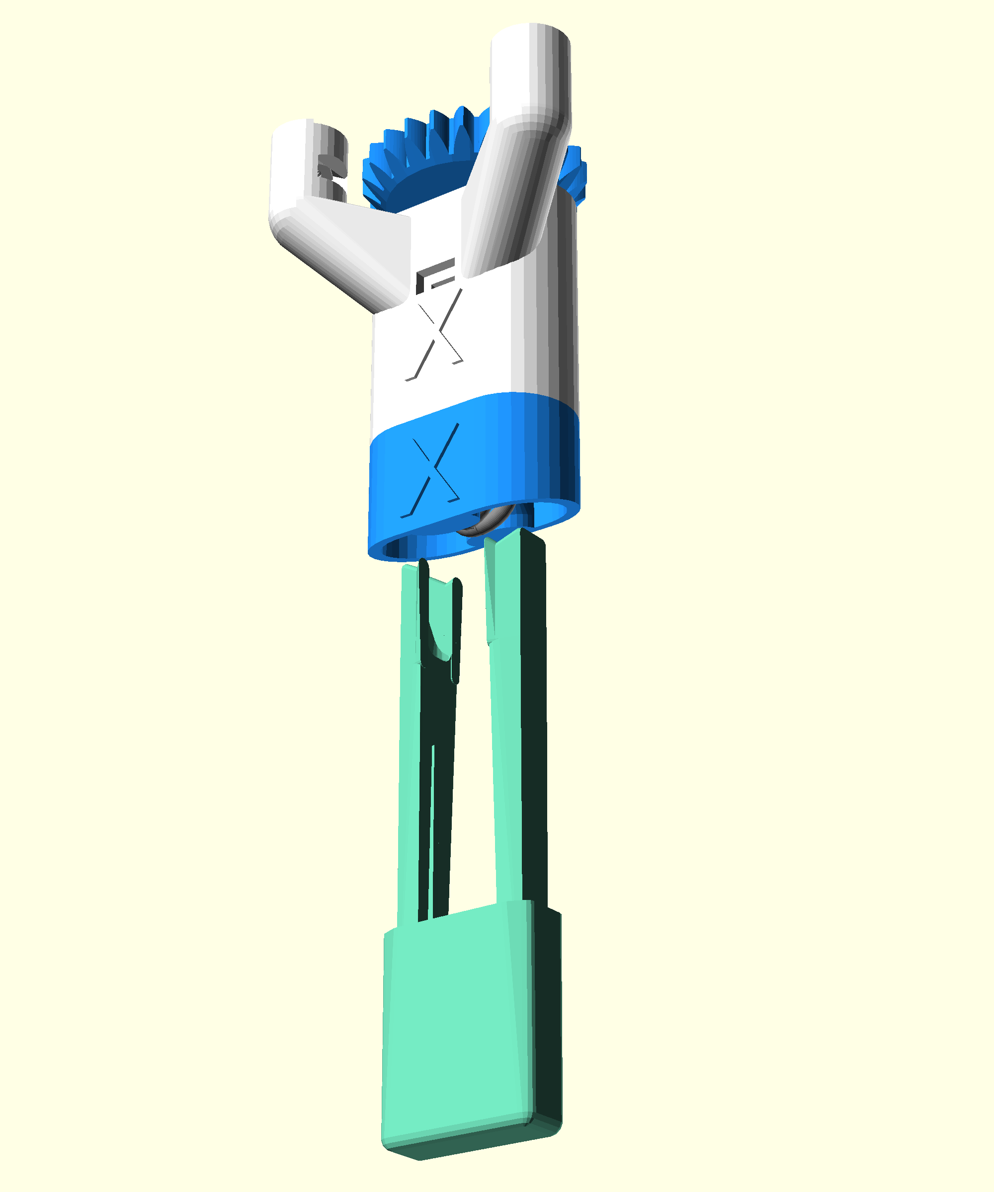
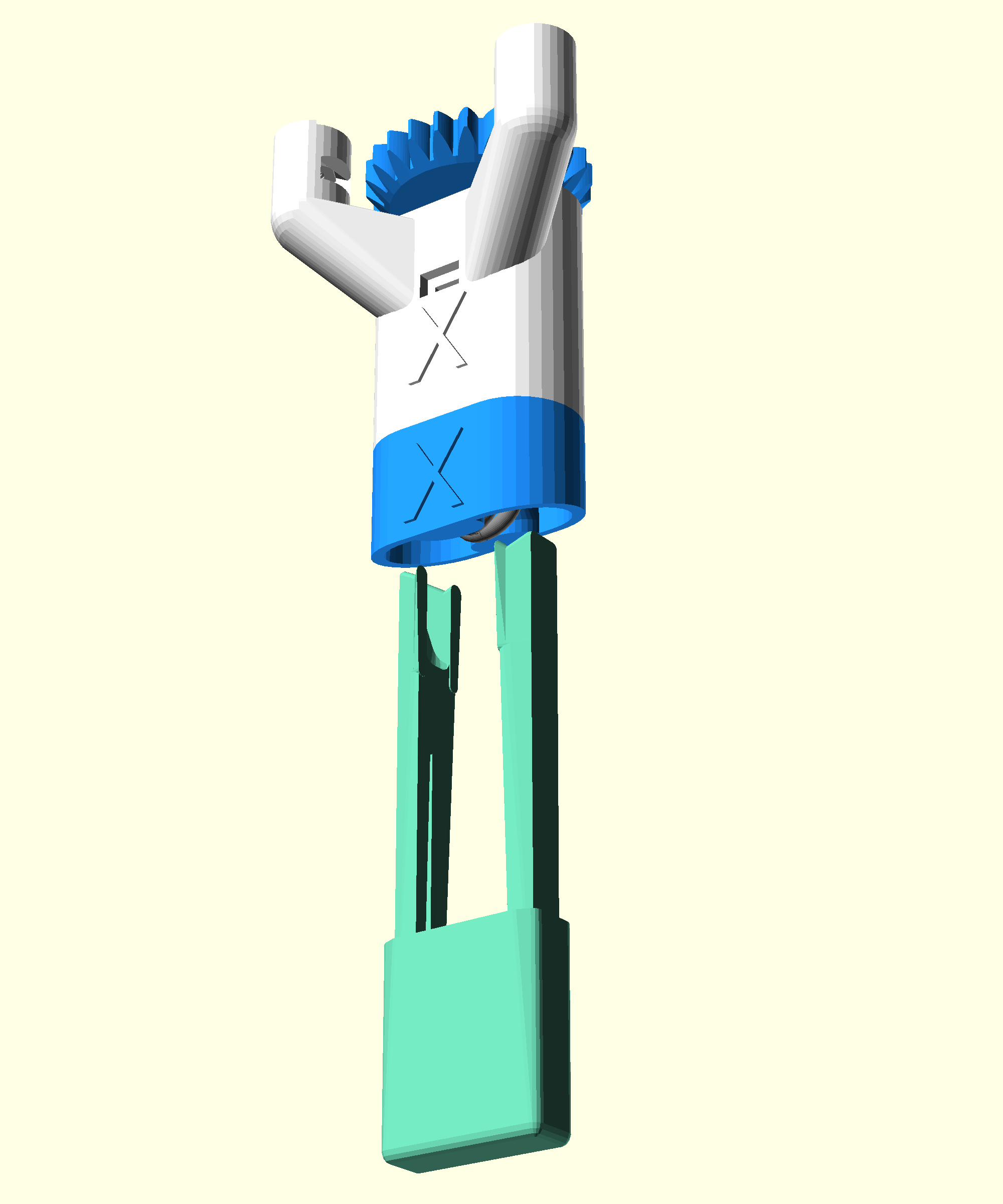
Step 8: Seat the foot
- If the foot did not click into place during actuator assembly align it and push it into place
- The foot should sit flush with the base of the microscope
- The front of the foot should align with the front of the actuator
Step 9: Repeat this process for Y and Z
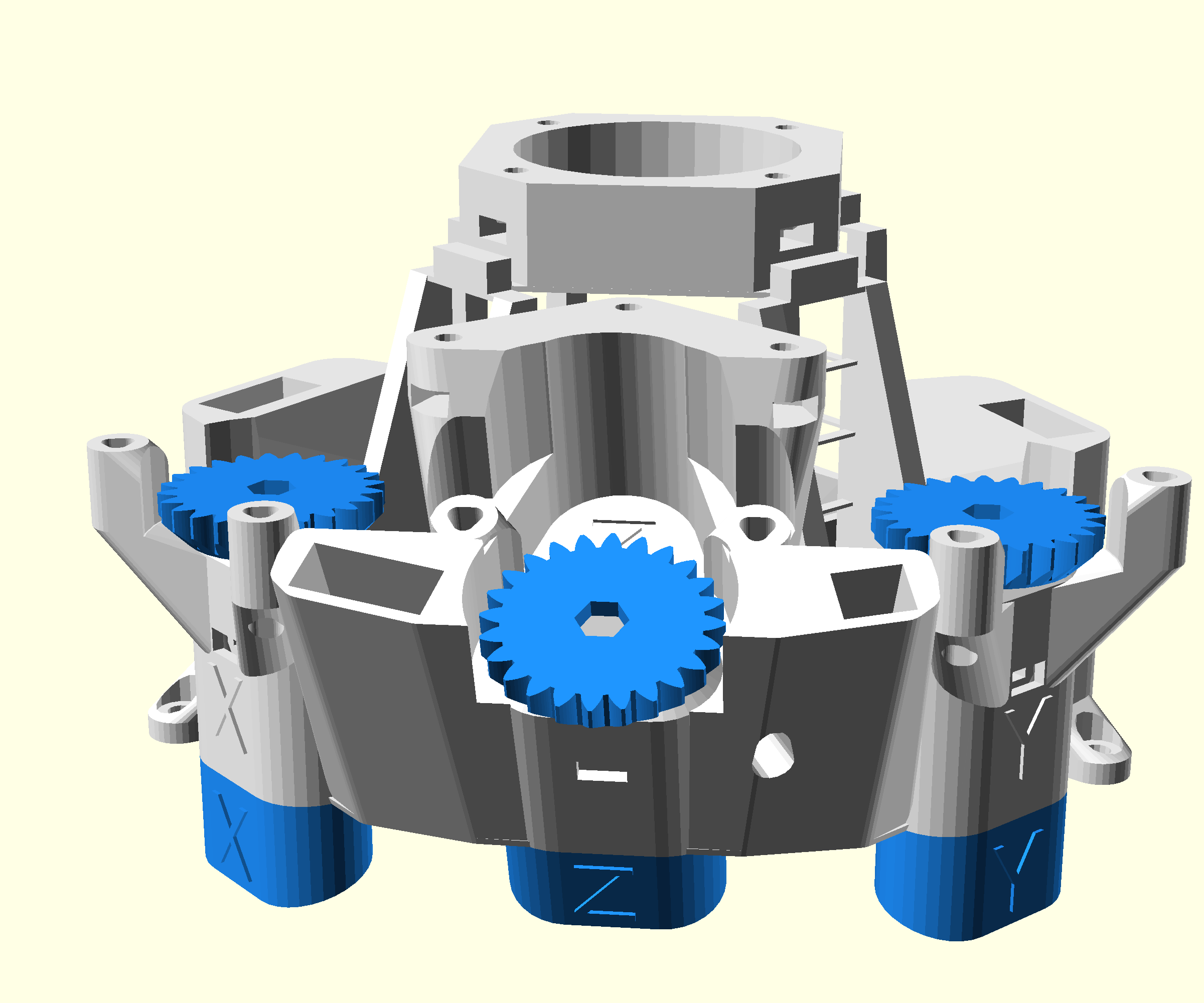
- Follow the same procedure to install the gear, foot and Viton band for the Y and Z axes
- Make sure that you have put a drop of light oil on both of the threads
- Make sure that both feet are seated
- Make sure that each axis has two washers
Step 10: Centre the actuators
- Look through the hole where you inserted the brass nut into in the x actuator
- You should be able to see the screw thread of the hex bolt and part of the brass nut. You should not be able to see the plastic of the internal actuator column
- Rotate the gear until the hole in the inner actuator column is aligned with the slot in the outer casing
- Repeat for the Y and Z axes