Complete the wiring
The microscope must be completed by mounting the motor driver electronics and the Raspberry Pi, connecting the motors to the motor driver, and connecting the illumination to a power source. These instructions assume you are using a Raspberry Pi v4 and a Sangaboard v4 or v5. See the box below if you are not using these electronics.
Alternative electronics options
If you are using a version of the Raspberry Pi other than v4, you will need a different electronics drawer. The options are described in the customisation page. If you do not have a Sangaboard, you can make up a compatible solution from a microcontroller and separate driver boards. This is described in the motor electronics workaround page.
For this section you will need:
Printed Parts
Electronic Components
- 1 Raspberry Pi
- 1 Raspberry Pi Power Supply
- 1 Sangaboard - If you cannot get a Sangaboard, you can put together workaround motor electronics instead.
Mechanical Components
Assembly video
Step 1: Connect the Raspberry Pi
- Take the electronics drawer you printed earlier and push the Raspberry Pi into place so the connectors show through the holes.
- Secure the Raspberry Pi in place with two self tapping screws
- Insert the ribbon cable from the optics module into the camera port of the Rasberry Pi, ensuring the contacts are on the opposite side from the clasp. There are detailed instructions on the Rasbperry Pi website.
Step 2: Upload the Sangaboard firmware
You will need to ensure the Sangaboard has the correct firmware and bootloader before it can be used. This is often easier to do before mounting it.
Sangaboard v3 and v4 have two micro-USB ports. One is for power only, the other is for data only. You must upload the firmware using the "data" port.
- Plug the Sangaboard into a computer, using the "data" micro-USB port. If it shows up as a Sangaboard (or as a USB serial port) when plugged into a computer, this means you already have a bootloader and can skip the next bullet point and go straight to uploading the firmware.
- For home-made Sangaboard v3 and v4 you need to follow the instructions in the repository to burn the bootloader.
- Once you have the correct bootloader, you must follow the instructions in the repository to upload the firmware.
Step 3: Connect the Sangaboard
- Mount the Sangaboard onto the Raspberry Pi GPIO pins, ensuring that the ribbon cable from the optics module passes through the slot.
- Secure the Sangaboard in place with two self tapping screws
- Push the motor cables into their labelled connectors. Make sure the motor from the correct axis on the microscope goes to the correct port.
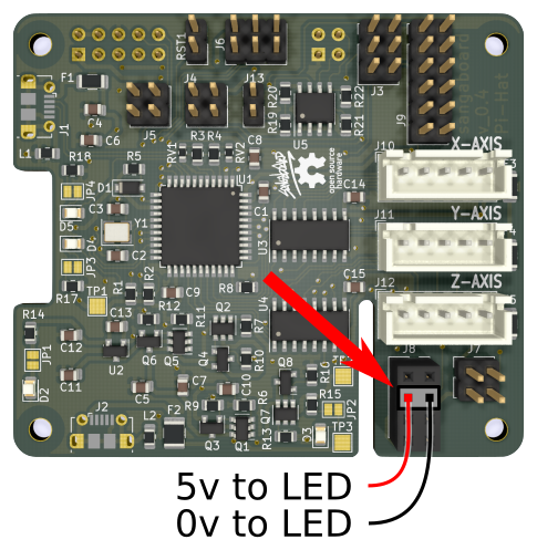
Step 4: Connect the LED to the Sangaboard
- Insert the 2-pin male connector into the 4x2 way female header on the Sangaboard.
- If you are not using a Sangaboard v4, you can also connect the LED to the Raspberry Pi

Step 5: Mount the electronics drawer
- Place an M3 nut into the slot just inside the hole in the front of the microscope base.
- Place another M3 nut into the slot above the Sangaboard power connector on the electronics drawer.
- Slide the electronics drawer into the microscope base making sure not to pinch any wires.
- Hold the electronics drawer in place with two M3x10 cap head screws which should screw into the two nuts.
Step 6: Wiring Complete
To power up your microscope you will need a power supply.
The power supply may change if you have used a different option for the motor electronics, so check what is required by your motor driver board. Some motor electronics options (Sangaboard v4 and v5) will power the Raspberry Pi, others may require separate power supplies for the Raspberry Pi and the motors.