Wire up motor electronics without a Sangaboard
This page describes how to connect the microcontroller and three motor driver boards, to make a Sangaboard-compatible motor control solution without custom PCBs.
For this section you will need:
Tools
Consumables
- A little heatshrink tubing - Electrical tape can be used if heatshrink is not available.
- A little solder
Electronic Components
Step 1: Wire up the boards
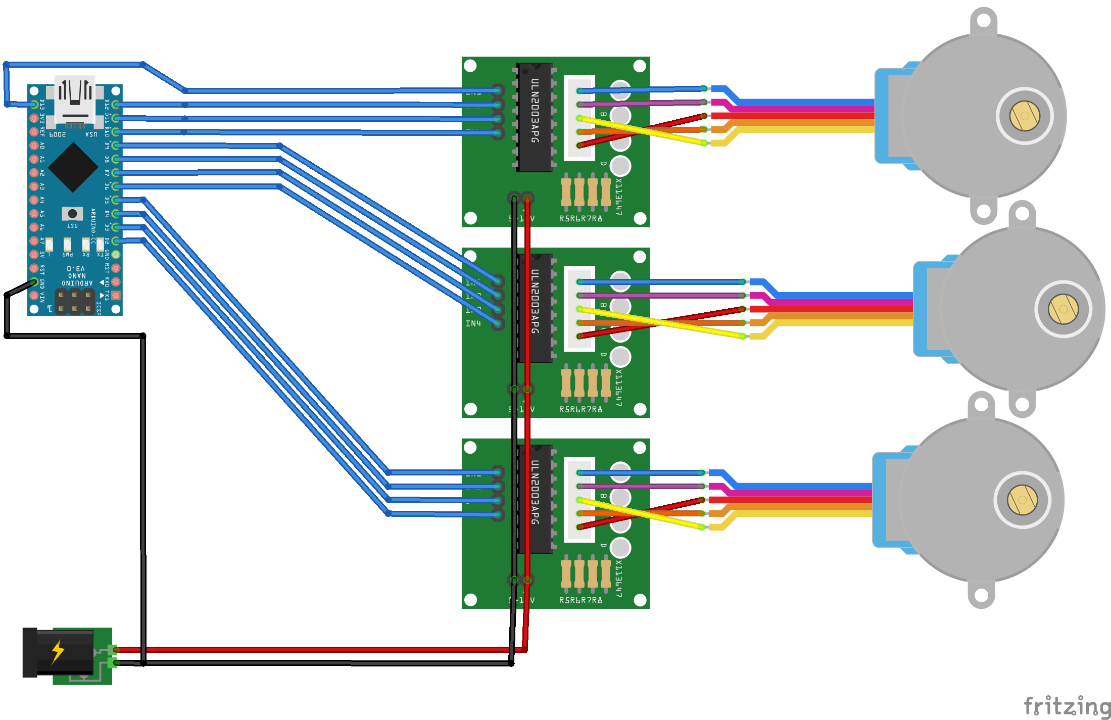
Each of your motors should have come with a driver board. You should wire these up to an Arduino Nano using jumper cables as shown in the diagram below:

The motor order is x-motor, y-motor, z-motor from top to bottom of this diagram.
Step 2: Wire up the power
We use a soldering iron to create the power cables.
To power the boards you need a 5V voltage source. We create this from a USB power supply.
- Tun on the soldering iron to the correct temperature for your solder
- Cut the end off the cable with wire cutters
- Strip back a portion of the outer cable
- Locate the Vcc (usually the red wire) and GND wires (usually the black wire)
- Cut one end off 7 jumper cables. (Preferably 4 black and 3 red)
- Solder 4 of these cables to the GND cable of the power supply
- Solder the other 3 to the Vcc cable of the power supply
- Protect the joints with heatshrink tubing.
- Connect up the power (with the supply off) as shown in the diagram above.