
Assemble the basic optics module
The imaging optics for this version of the microscope consist of a Logitech C270 webcam and the lens from the camera. To create a microscope, the wide angle lens is reversed and separated from the camera. This makes quite a good microscope objective with a field of view about 1000×560μm, similar to using a 20x objective.
For this section you will need:
Tools
Printed Parts
Electronic Components
Mechanical Components
- 1 M3 nut
- 1 M3x10 cap head screws
- 4 No 1 self tapping screws - Recovered from C270 camera dissassembly
- 2 No 2 6.5mm self tapping screws
These instructions guide you through assembling the manual microscope with most compact and low cost optics system, using a Logitech C270 webcam in a basic optics module.
STLs for using an Arducam B0196 webcam or a Raspberry Pi camera v2 in a similar module can be found in the list of basic optics modules on the optics customisations page.
Step 1: Visually inspect the lens spacer
Take the lens spacer and confirm that:
- It has been printed in black

- It is dust free (You can blow air through to clean it)
- The central shaft is not obstructed by strings of plastic
Step 2: Push-fit the lens
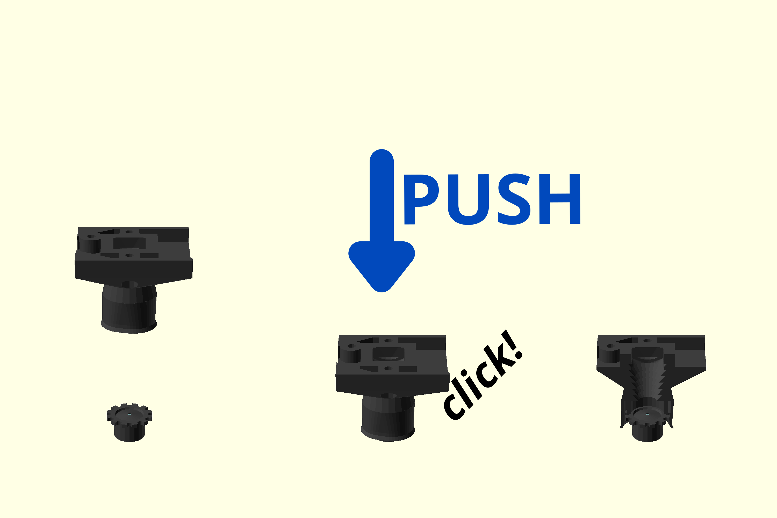
- Work out which side of the Logitech C270 Camera lens used to be facing the camera sensor (This is the side with more lens visible).
- Place the lens on a clean surface with the side that was next to the camera sensor on the bottom, and the wider knurled ring towards the top.
- Push the lens spacer down onto the lens until it clicks into place.
Step 3: Attach the camera board to the lens spacer
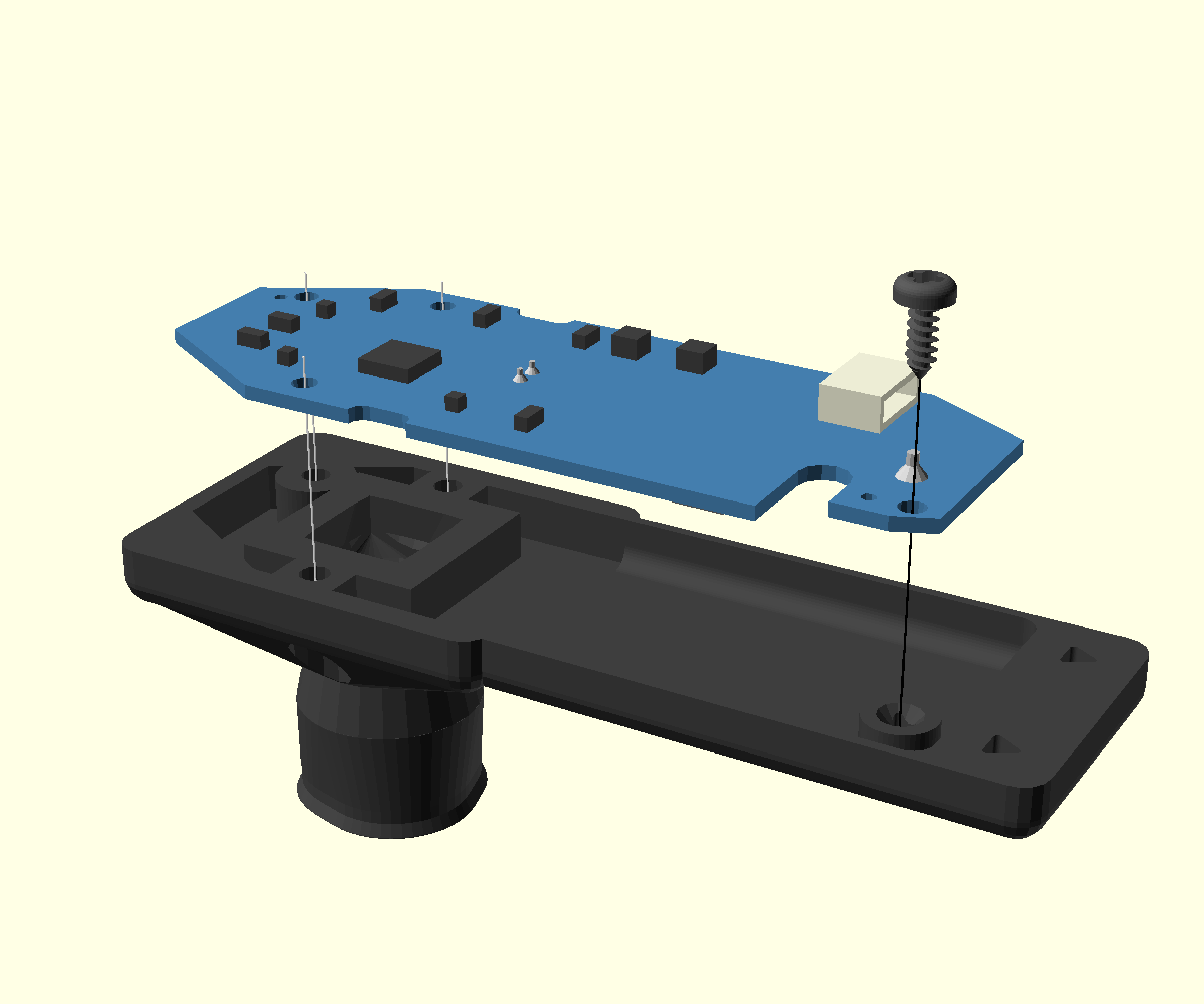
- Take the Logitech C270 camera board and place it on top of the assembled lens spacer, with the sensor facing down
- Align the four screw holes with the corresponding holes in the lens spacer
- Attach the C270 camera board using one of the No 1 self tapping screws that you saved from the camera disassembly, using a #0 Phillips screwdriver
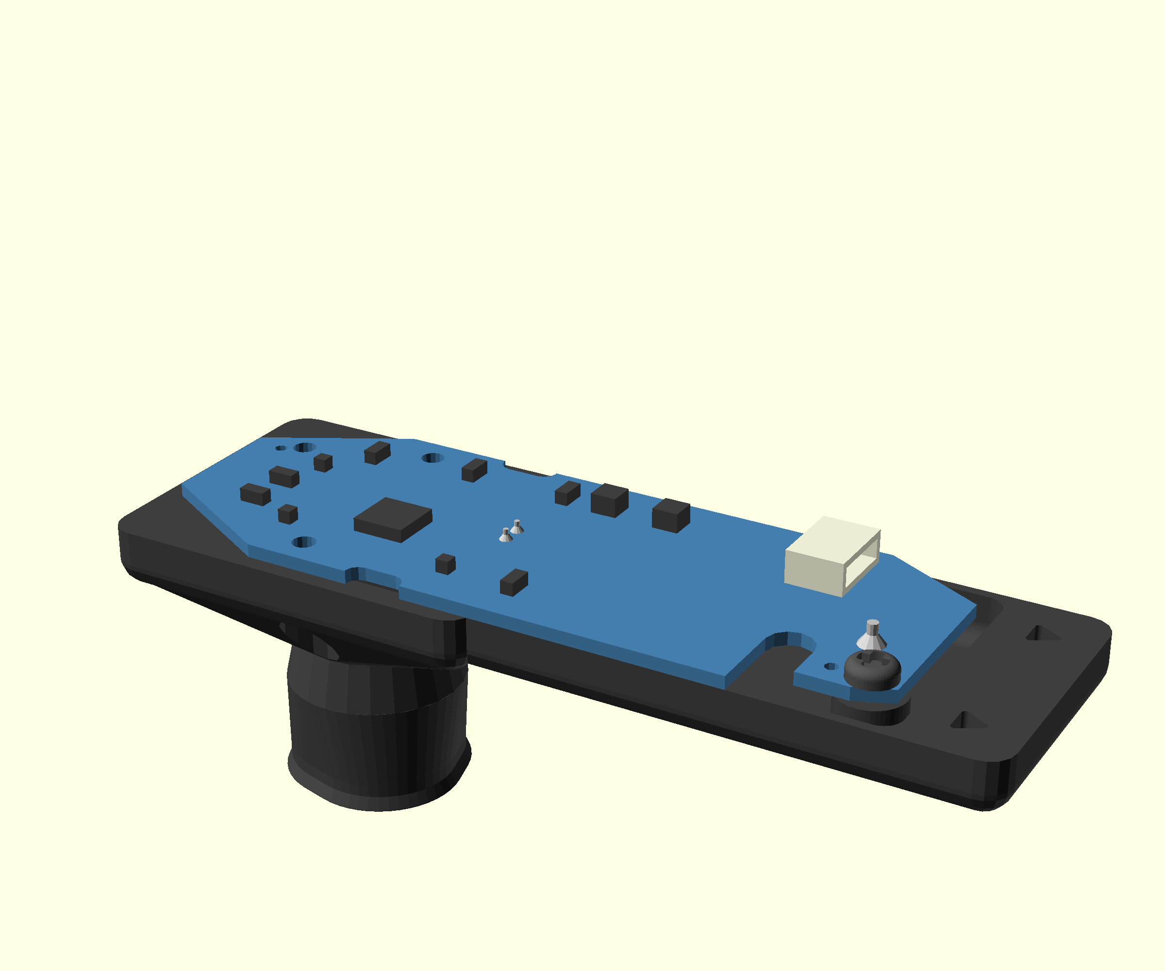
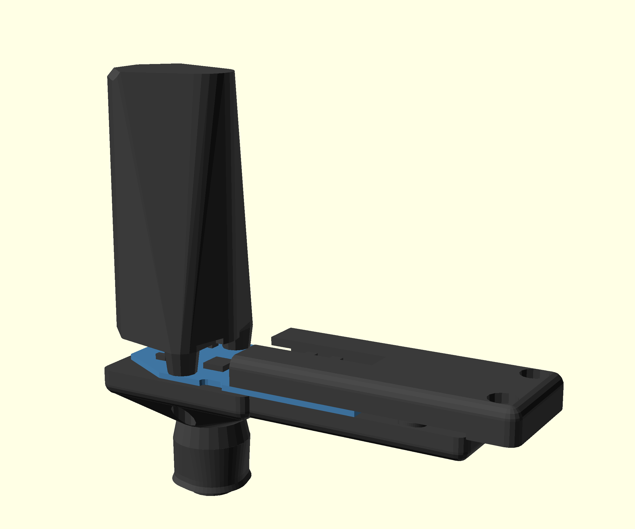
Step 4: Attach the assembled camera module
- Take the assembled camera and lens spacer and place it on top of the camera platform
- Use three of the No 1 self tapping screws that you saved from the camera disassembly to secure the three parts together using a #0 Phillips screwdriver
- Take care to not over torque the screws
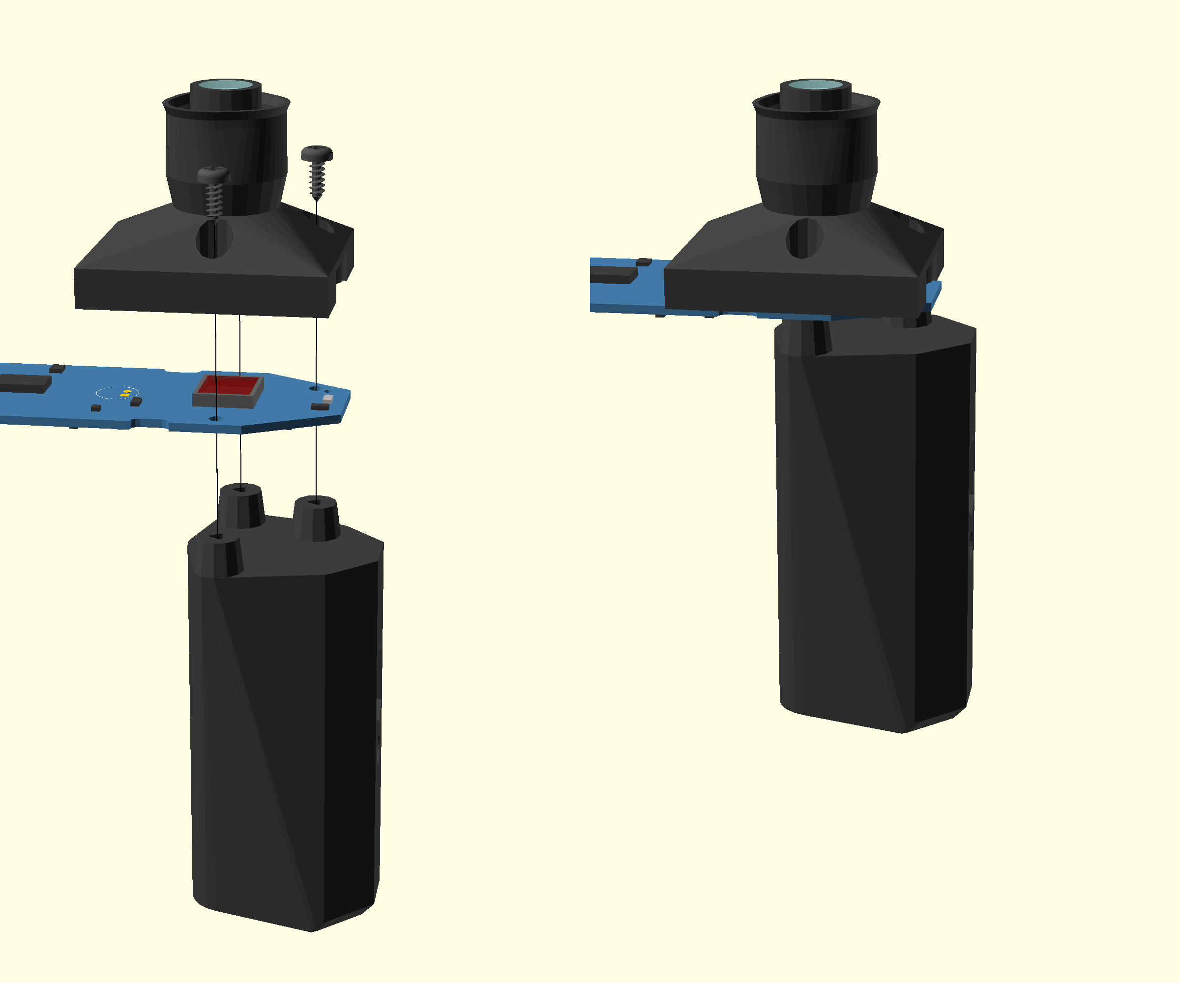
Step 5: Attach the camera backshell
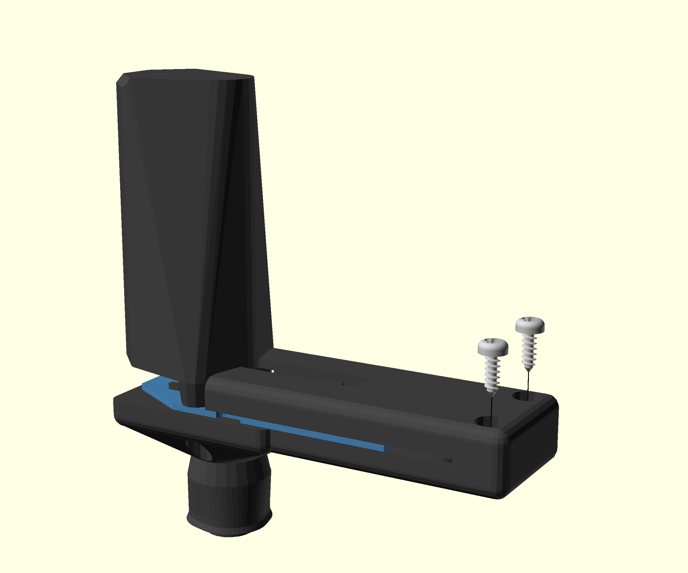

- Take the camera backshell printed part
- If it was printed with brim, make sure that any brim has been fully removed from the two 'forks'
- Turn the assembled camera and platform over
- Arrange the cables so that they are on top of the camera board and leading towards the camera platform
- Place the backshell over the camera board with the cable running out through the slot
- Slide the camera backshell into place to engage the 'forks' with the cut outs on the camera platform.
- Secure with two No 2 6.5mm self tapping screws using a #1 pozidrive screwdriver. If the screw holes do not align, check that the backshell is fully engaged on the camera platform and that it is not obstructed by remnants of any brim.
Step 6: Attach the mounting screw
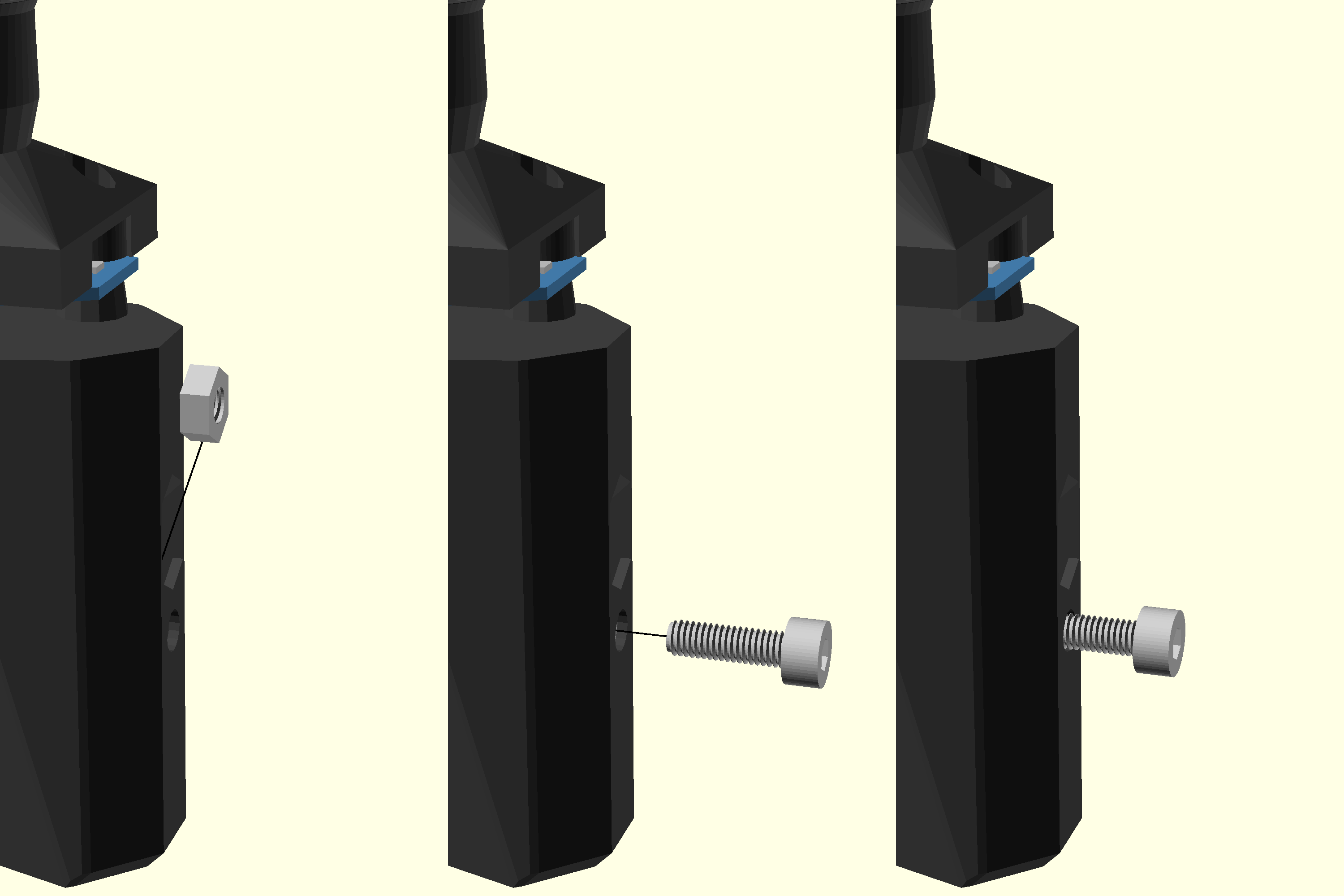
- Take an M3 nut and push it into the nut trap from the top
- Take an M3x10 cap head screw and screw it into the nut.
- Only screw it in a couple of turns. About 5 mm of thread should still be visible
Set the complete optics module aside in a safe place.