
Sangaboard v0.5
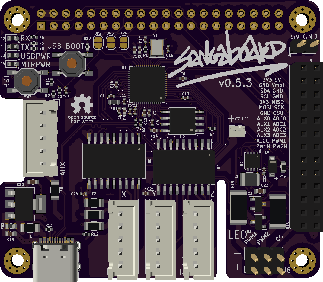
We use a custom open source motor board called the Sangaboard. The latest version is based on the RP2040 chip from raspberry pi and works as a hat for the Pi, eliminating the need for additional wiring. The board provides power to the pi so that only one USB-C power supply is required for the microscope (capable of at least 3A). Any version starting with 0.5 should work with this version of the microscope, most testing has been done with v0.5.3. Sangaboards are currently available from Taulab, see the part link at the bottom of this page.
The Sangaboard uses surface mount components and custom boards, this makes it hard to solder your own. While the board design and schematics are available openly, we do not recommend making your own unless you have the appropriate tools and experience. If you cannot get a Sangaboard, you can build your own Sangaboard-compatible motor controller.
There are also various older sangaboard versions that are not recommended for the current version of the microscope. Most of them are still capable of running the latest firmware and controlling the motors, but result in messier wiring and don't fit as neatly in the microscope case.
Note on Sangaboard v0.5
The Sangaboard v0.5 from our preferred supplier has 11mm tall header connectors. If you purchase a board from another supplier and they use standard 8.5mm headers you will need to print a different electronics drawer
Features
Sangaboard v0.5 introduces some important new features
Motor control
Like earlier versions, the Sangaboard reads commands via a serial connection and controls the motors driving the microscope stage. This is handled directly within the default microscope software.
Microscope extension
To make use of more advanced features in the microscope's software, version 2, a Sangaboard extension to the microscope software has to be installed. For more details and installation instructions, see the extension repo. This is likely to be superseded in v3 of the software.
Aborting moves
The new firmware supports aborting moves in progress. To abort a move, open the Sangaboard extension tab and use the Stop Stage button. This feature will be built in to v3 of the software.
4th motor
This board can control 4 motors to support more complex variations of the microscope in the future. 4th motor control is not currently exposed within the standard microscope software, but microscope extensions can access it using n_motors 4 command to enable the 4th motor and then sending move commands with 4 displacements. See firmware source for details.
Illumination control
This new board can also control the illumination. In the most common configuration, an LED on a carrier board is connected to the CC (constant current) +- pins on the LED header. By default this will provide approximately 30mA of current for the LED. The current for this LED can be controlled through the Sangaboard extension UI in the range of 0-100 mA.
For higher power LEDs, there are 2 PWM based channels driven by MOSFETs on the board and these are designed to provide up to 1A of current to the LEDs. To protect the board from potential damage, there is 1.5 Ohm current limiting resisor in series with the PWM LEDs. For advanced users wishing to experiment with different currents/LEDs, this resistor can be bypassed using a solder jumper on the bottom of of board. The PWM frequency and duty cycle (brightness) can be adjusted in the Sangaboard extension. The frequency can be increased up to 1MHz if there is flicker visible in the recordings (mostly at high framerates), but the brightness resolution is reduced at very high frequencies (32 steps at 1MHz). In testing no flicker was visible even at much lower frequencies. For extended use of the PWM system at high powers a heatsink is highly recommended.
One-click firmware upgrades
The Sangaboard extensions allows the application of firmware upgrades with a single button via the UI. Internally, this is handled by an SWD connection to the Raspberry Pi. If you wish to use the Pi's SWD for a different device, cut the cuttable traces between JP3 and JP4. Cutting JP2 will disconnect the RP2040 reset pin from the Pi's GPIO23.
Expansion header
Unused pins on the RP2040 are routed to the expansion header on the right side of the board. This can be used to connect to any additional devices which can then be integrated to the firmware. See the board design and schematics for more details on the wiring and the firmware for details on how to add custom features.
Stackable Pi header
To allow use of the available Raspberry Pi GPIO pins, the connector on the board is stackable and all Pi's GPIO pins can be accessed. If you are using these pins to connect additional components, avoid connecting anything that might draw too much current (the single power supply is powering the pi, motors, and LED(s), so make sure total current does not exceed the rating of your power supply). The USB-C connector on the board is rated for 5A. Additionally, GPIO14 and GPIO15 are used for serial communication and cannot be used for other components. GPIO23-25 are used for upgrading firmware, if you do not need this feature you can cut jumpers JP2-4 (see section above for details).
Specifications
| Attribute | Value |
|---|---|
| Version | 0.5.3 |
Suppliers
| Supplier | Part Number |
|---|---|
| Taulab | Sangaboard v5 |