Reflection illumination
One of the best uses of the OpenFlexure Delta Stage is as a reflection illumination microscope. These instructions show you how to assemble the optical components.
Parts
- 2 M2.5 nut
- 2 M2.5 washer
- 4 M2.5x8mm screw
- 2 M2x6mm screw
- 1 M3 nut
- 3 M3x8mm screw
- 1 Raspberry Pi camera v2
- 2 banana plug
- 1 beamsplitter filter
- 40 cm of black 0.5A instrument wire
- 1 condenser lens
- some electrical tape
- 1 emission filter
- 1 excitation filter
- 1 objective lens
- 1 power supply
- 40 cm of red 0.5A instrument wire
- some solder
- 1 star LED
- 1 tube lens
Tools
- 1 1.5mm hex screwdriver
- 1 2.5mm hex screwdriver
- 1 2mm hex screwdriver
- 1 oil glass cutter
- 1 soldering iron
Printed tools
3D printed parts
- 1 camera cover
- 1 filter cube - Print in black.
- 1 reflection illumination condenser - Print in black.
- 1 reflection illumination holder - Print in black.
- 1 reflection optics module casing - Print in black.
Method
Step 1: Wire the star LED
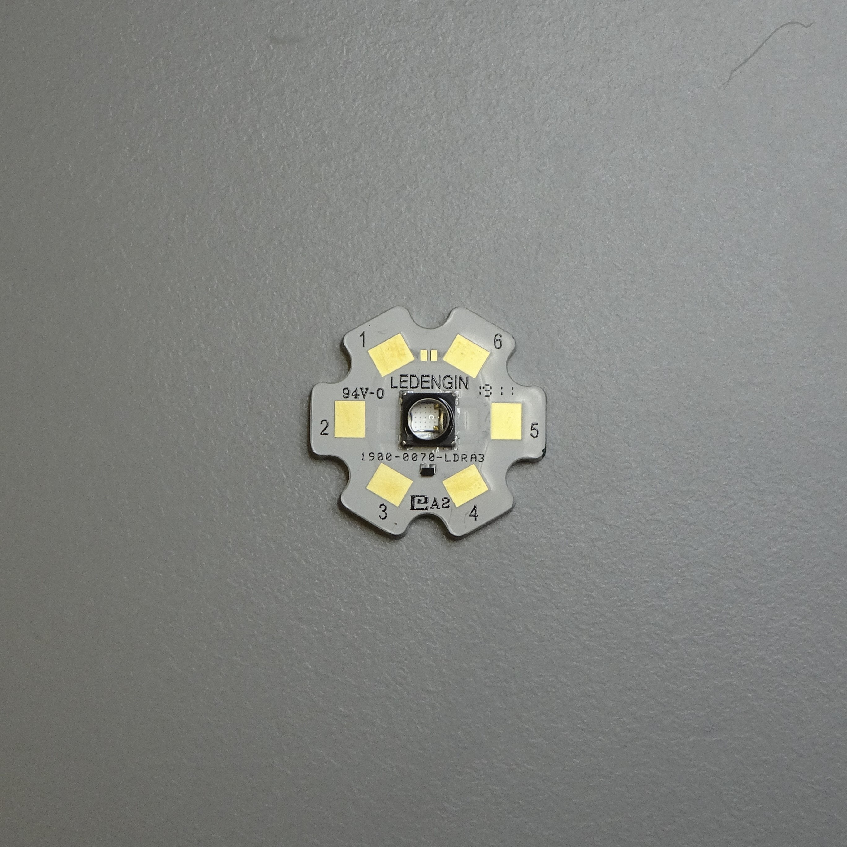
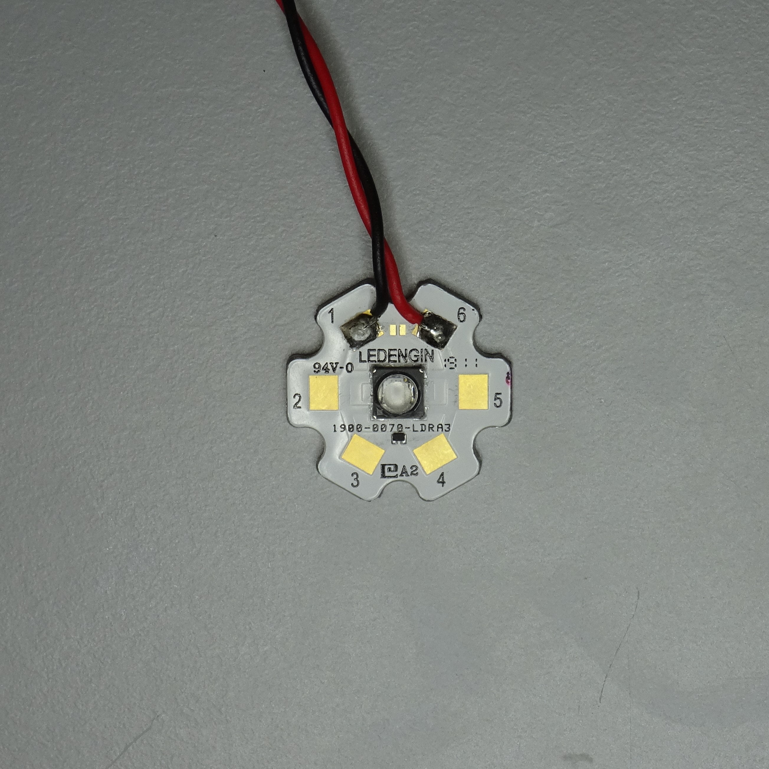
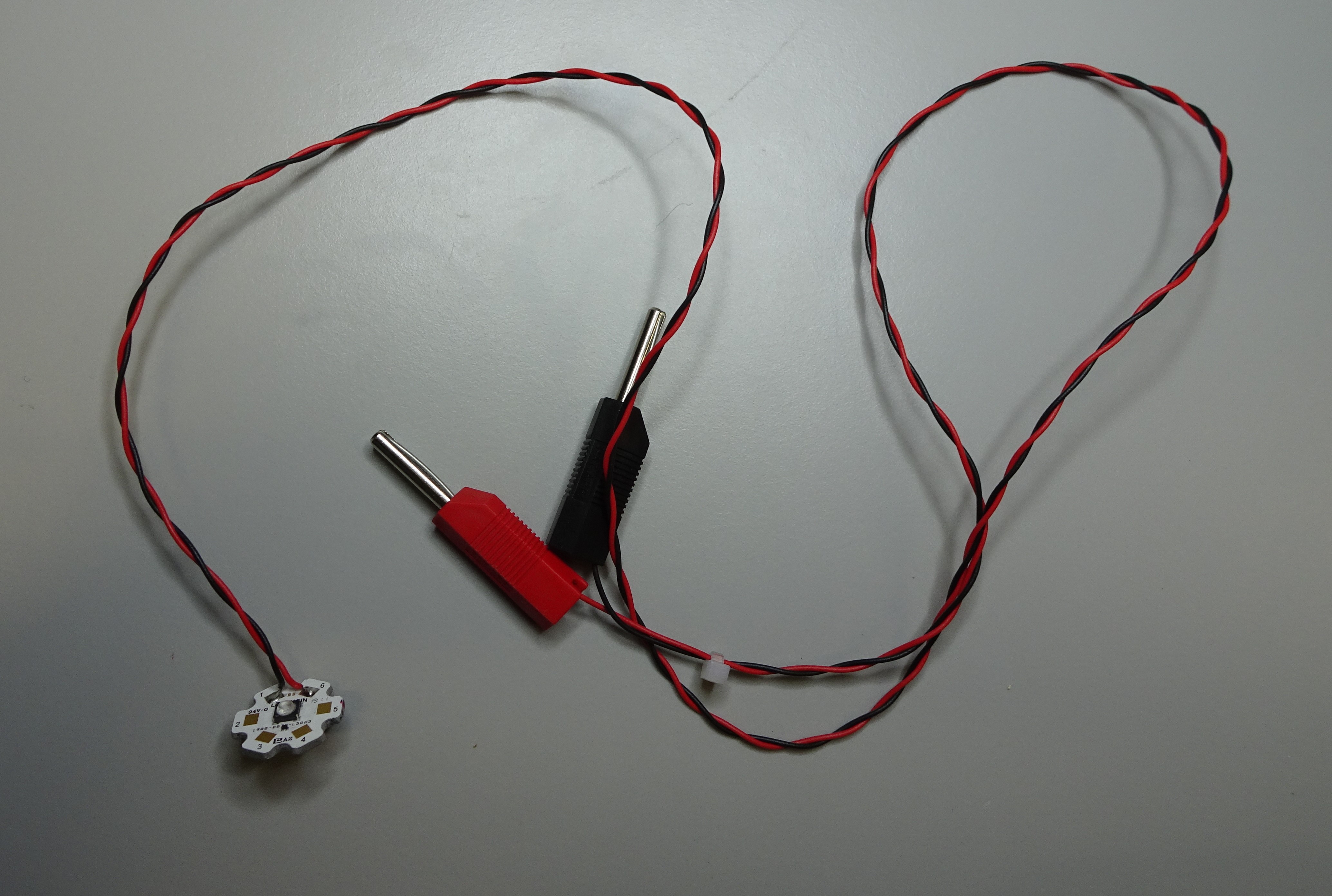
Solder the red 0.5A instrument wire and the black 0.5A instrument wire to the star LED, following the manufacturer's instructions for which pad to solder to, using a soldering iron and some solder. Be careful to keep the solder joint as small as possible. At the other end, attach connectors for connecting to your power supply. In this example, we use banana plug.

Step 2: Insert the condenser lens
Put the condenser lens on the lens tool with the convex side face down.
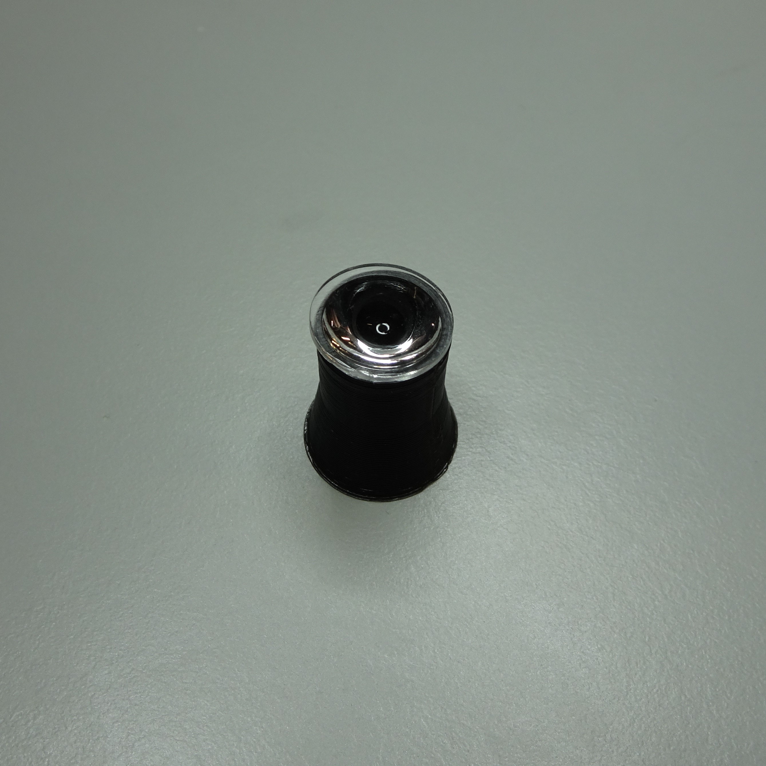
Push the reflection illumination condenser down onto the lens. Check it is pushed all the way in and it is flat.
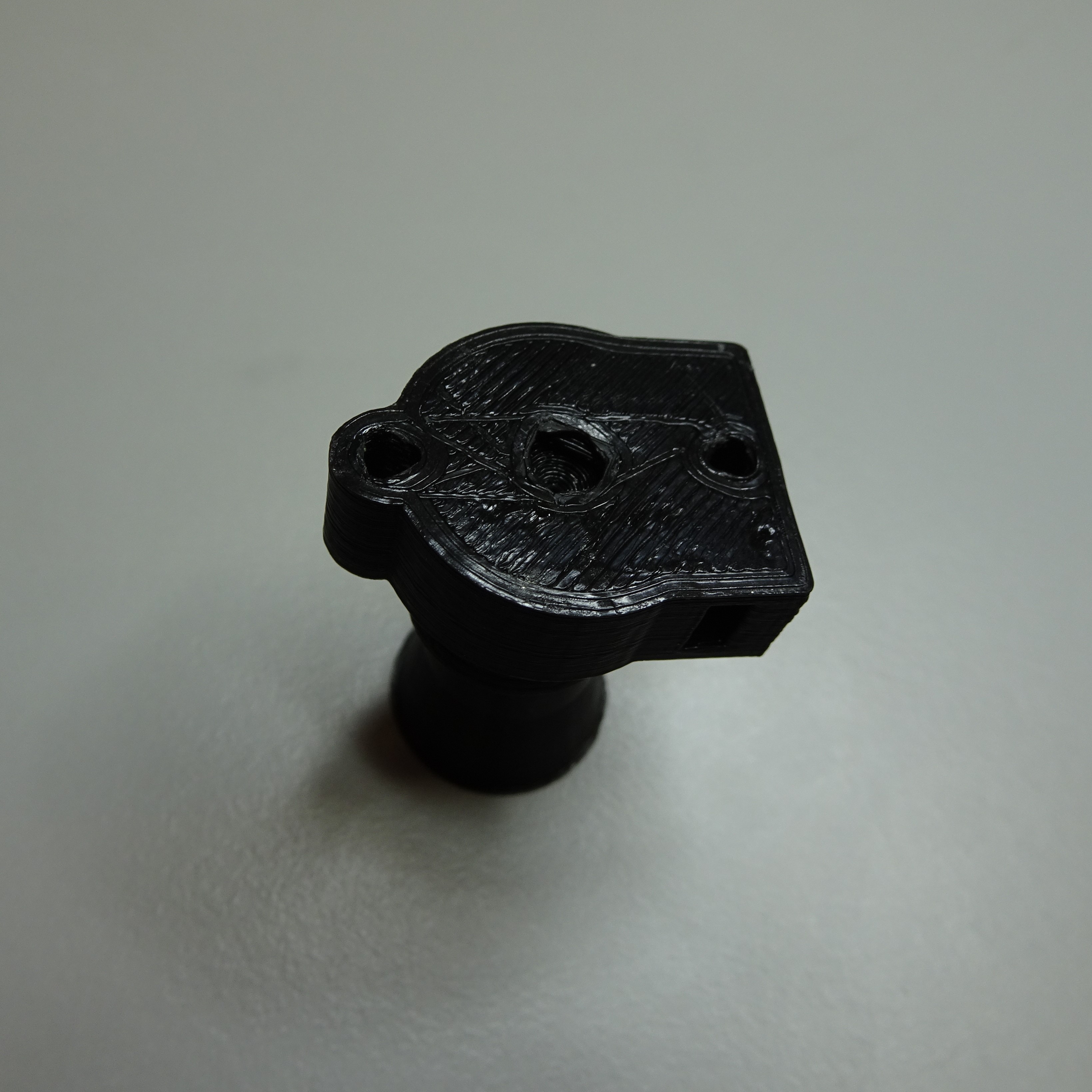
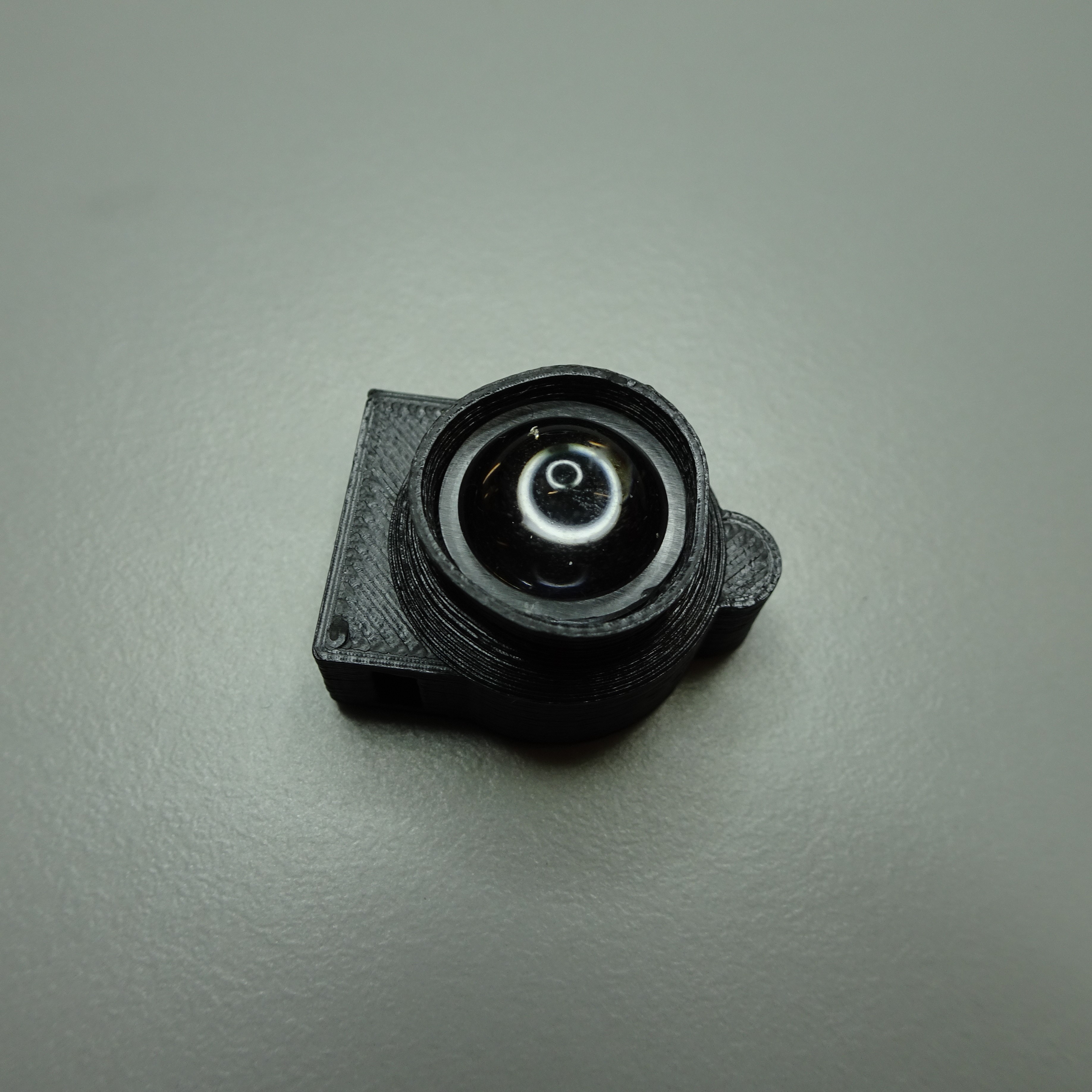

Step 3: Attach the LED
Attach the star LED to the back of the reflection illumination condenser with two M3x8mm screw using a 2.5mm hex screwdriver. Make sure the wires come out from near the bottom.
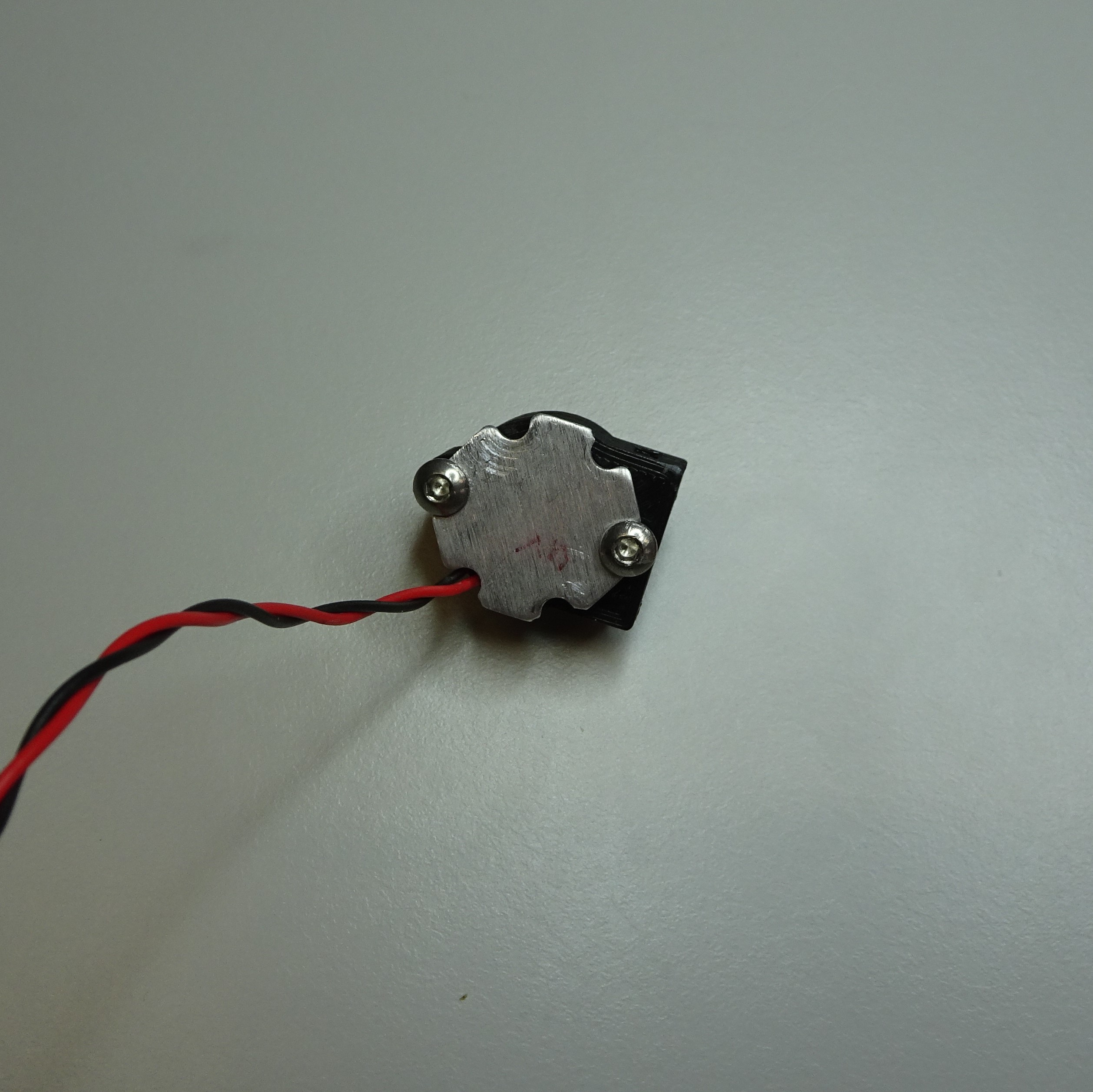
Step 4: Insert the slip plate screws
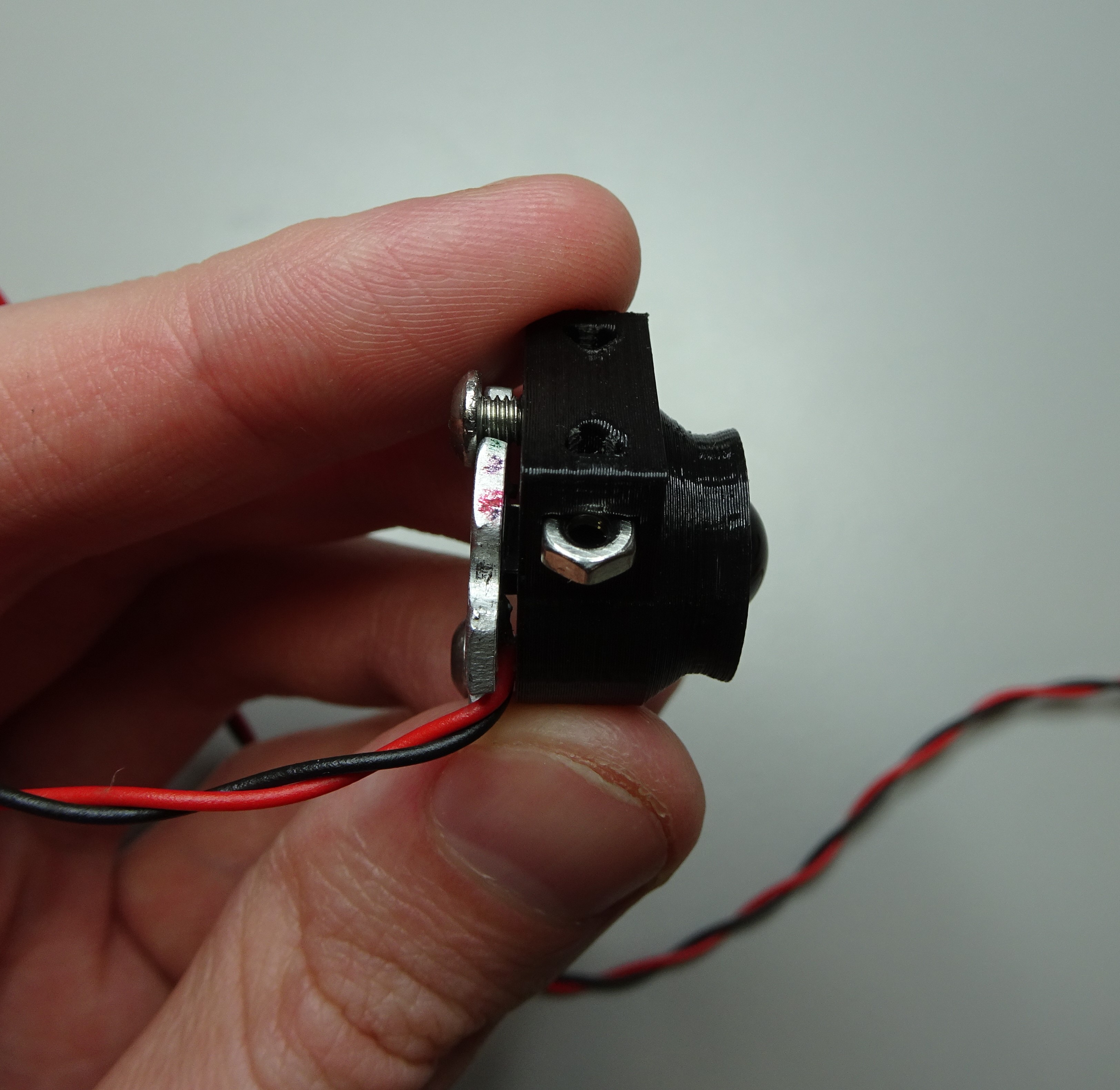
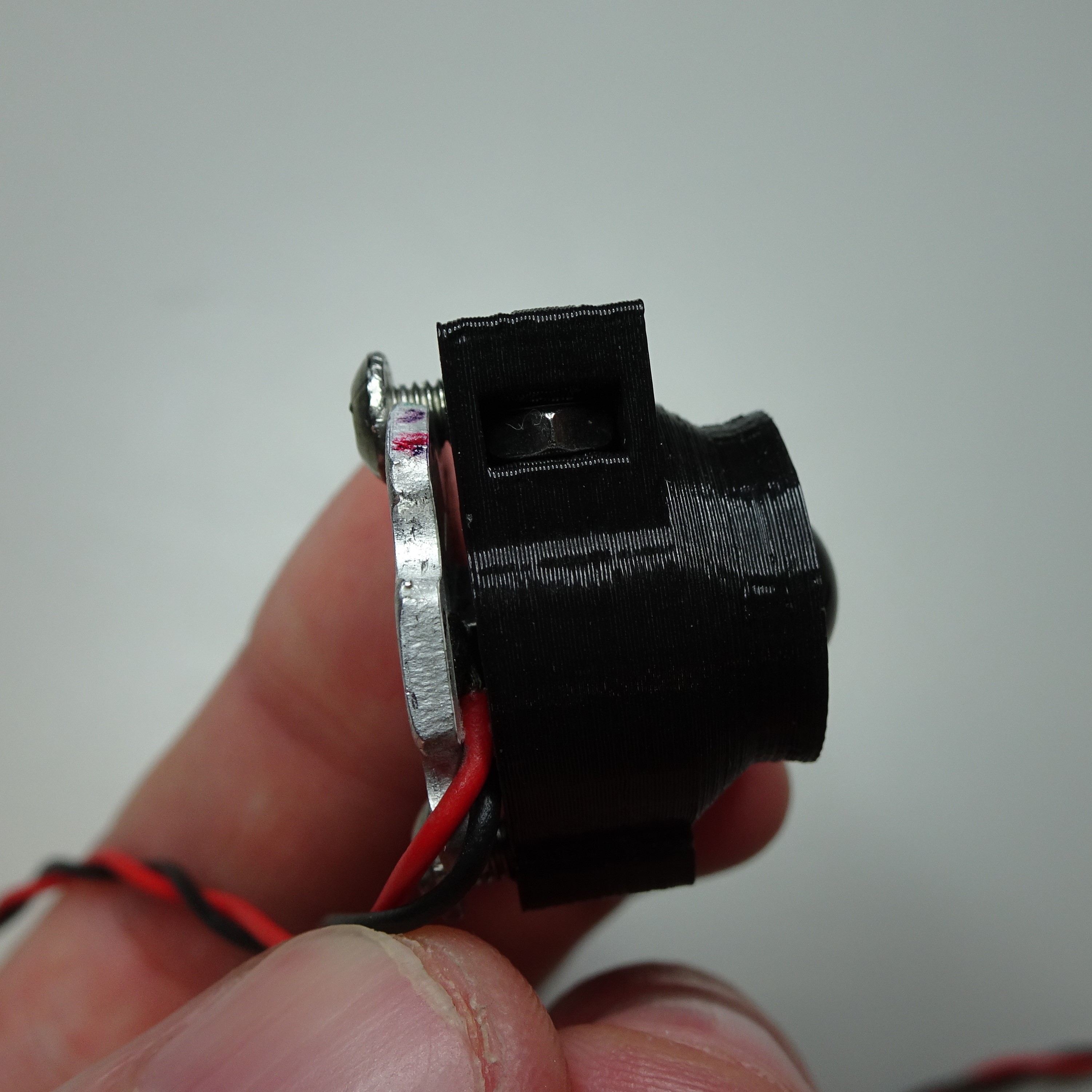
Push the M2.5 nut into the slots on the top of the reflection illumination condenser.

Step 5: Cut the glass filters
Cut the excitation filter, emission filter and beamsplitter filter (it's easiest with an oil glass cutter). Currently there are only .stls for 1.5mm thickness glass filters, although it possible to change this in the .scad.
| Filter type | Width (mm) | Length (mm) |
|---|---|---|
| Excitation | 12 | 15 |
| Emission | 12 | 15 |
| Beamsplitter | 12 | 18 |
Step 6: Slot the filters into the filter cube
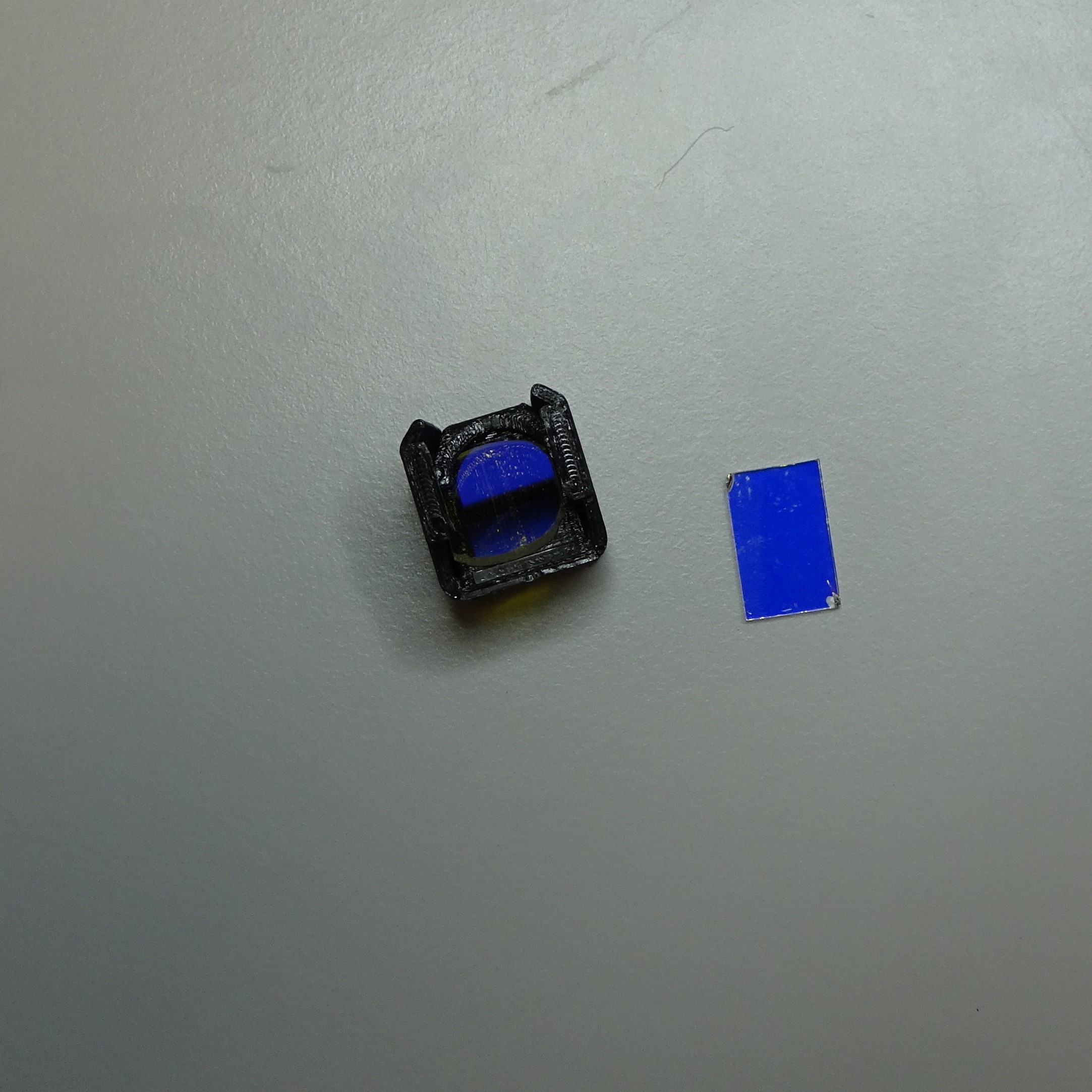
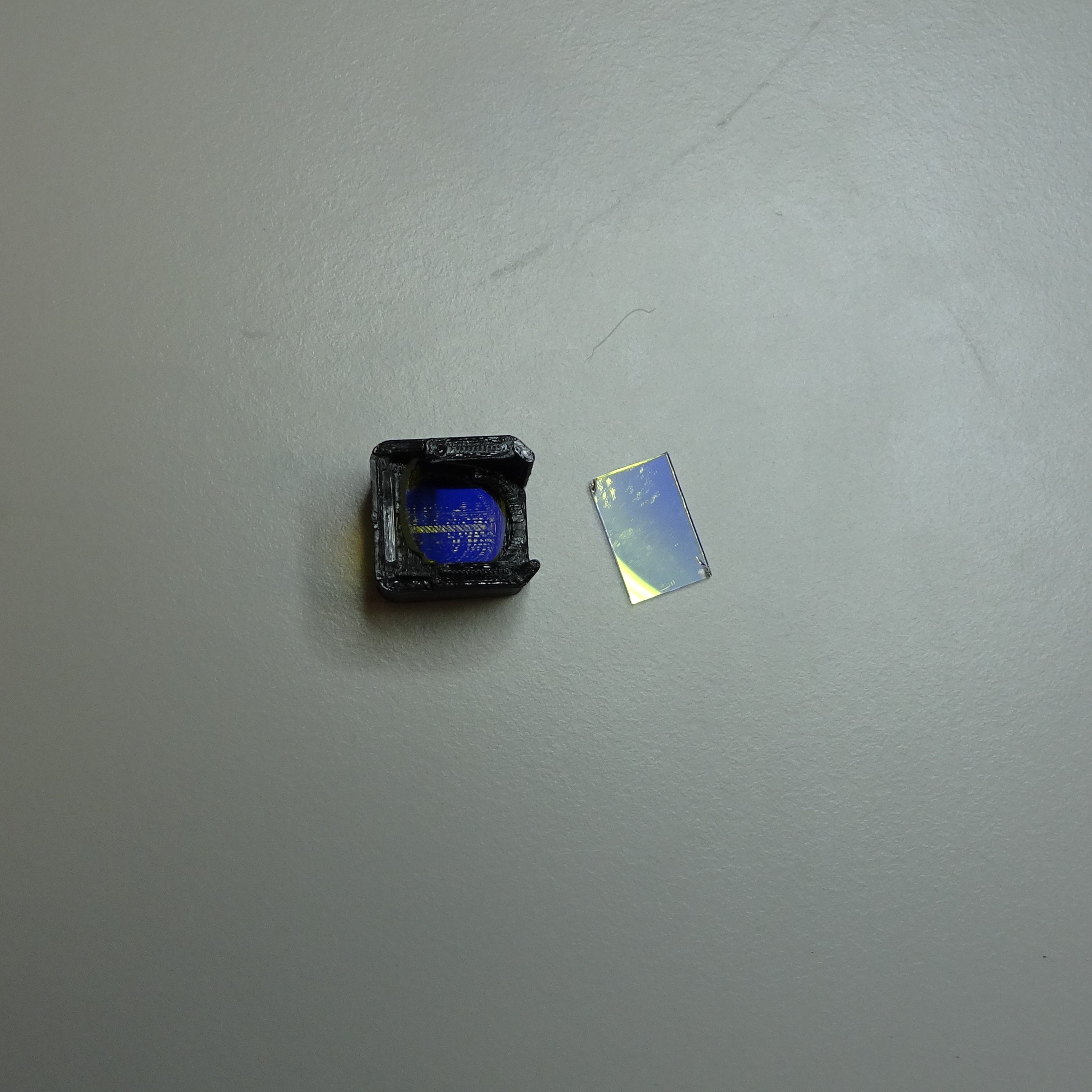
Push the emission filter into the bottom of the filter cube. It should be tight but be careful not to break the glass filter. You might need to file down the slot if there are printing errors.
Push the beamsplitter filter into the 45° slot. Again it might be tight, and you might need to use a file to ensure you can fit it in.


Step 7: Clean the optics module casing
After printing the reflection optics module casing there may be strings or dust. Clean these out so they won't block the light or fall onto the camera sensor.
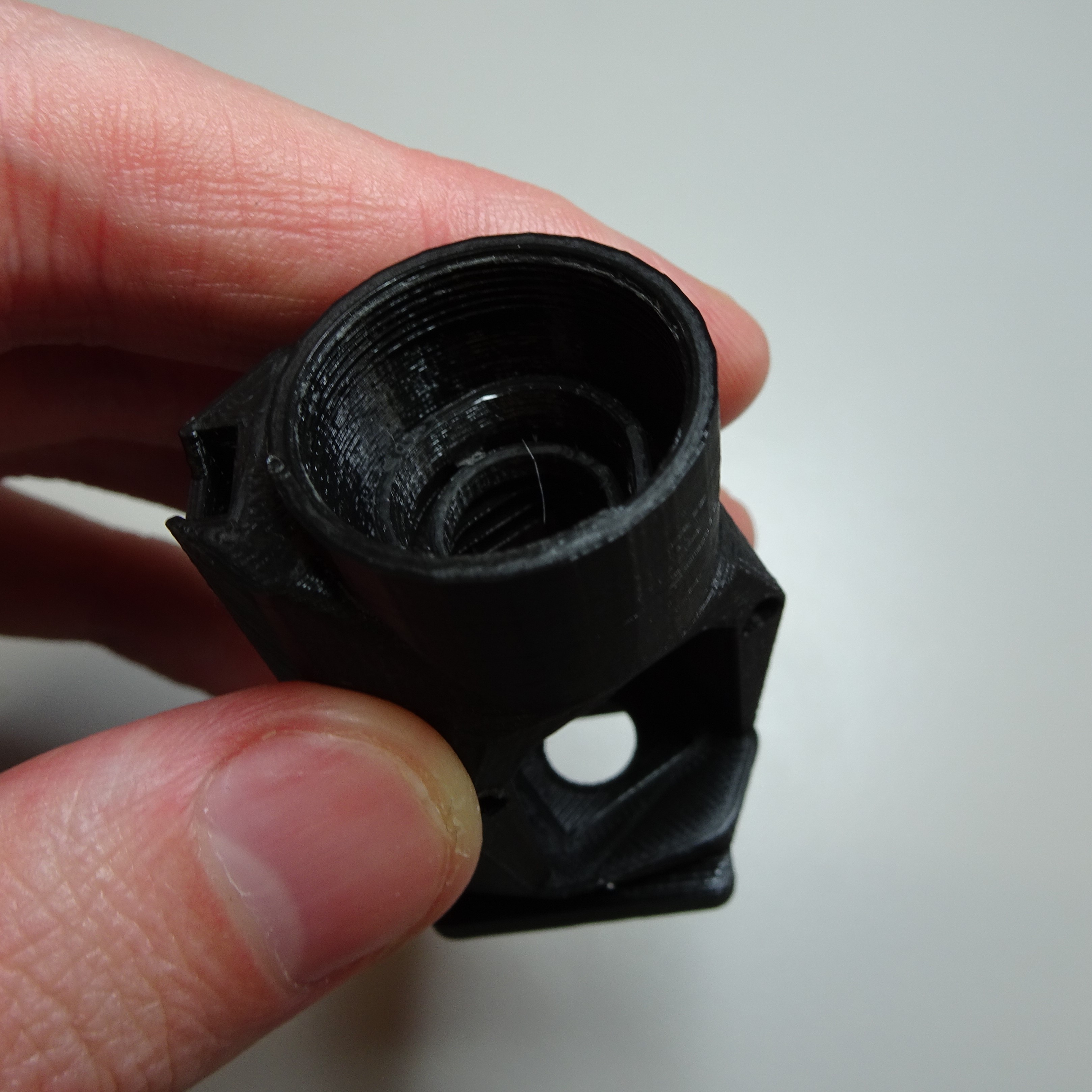
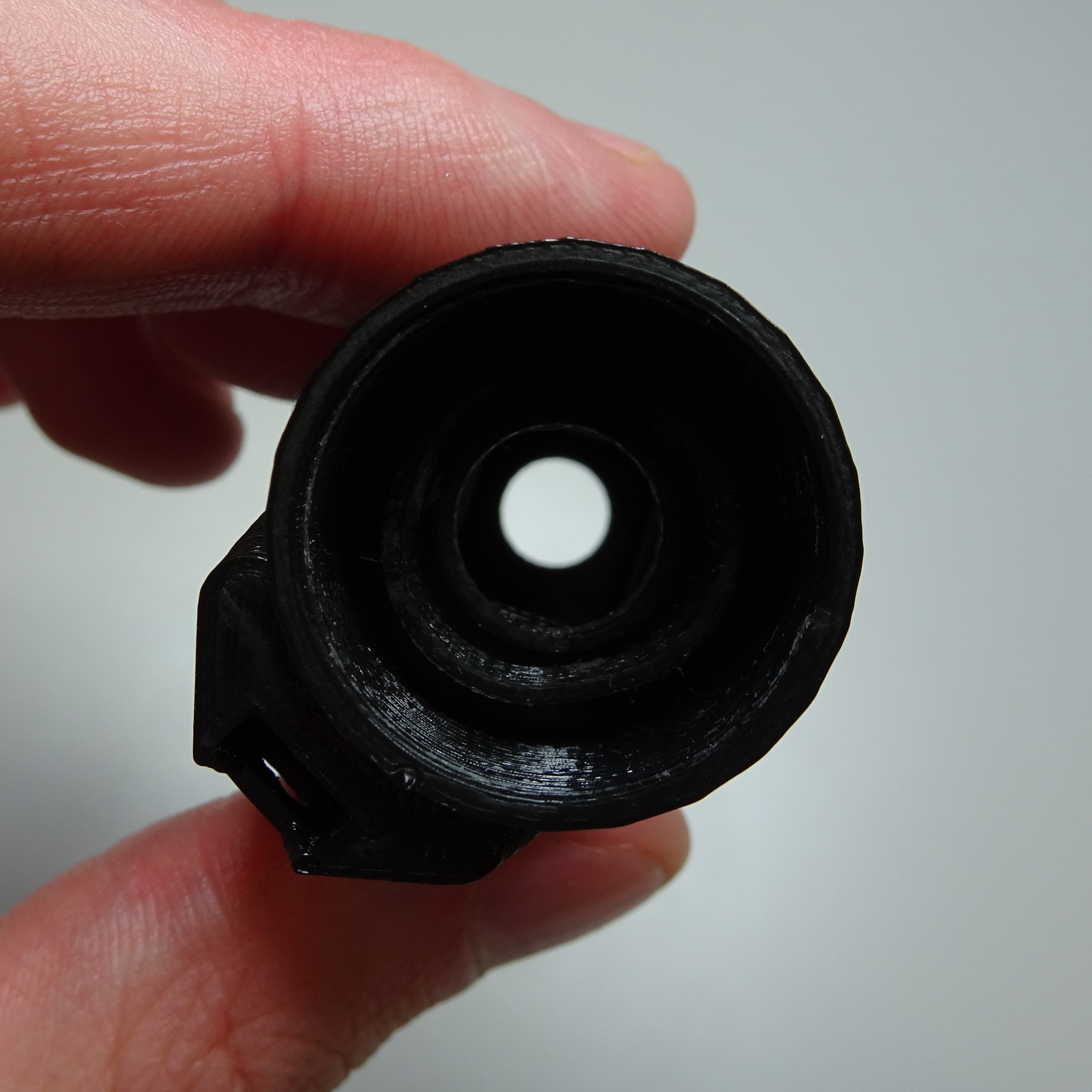

Step 8: Attach the objective screw
Slide a M3 nut into the slot at the top of the reflection optics module casing and screw a M3x8mm screw into it using a 2.5mm hex screwdriver.
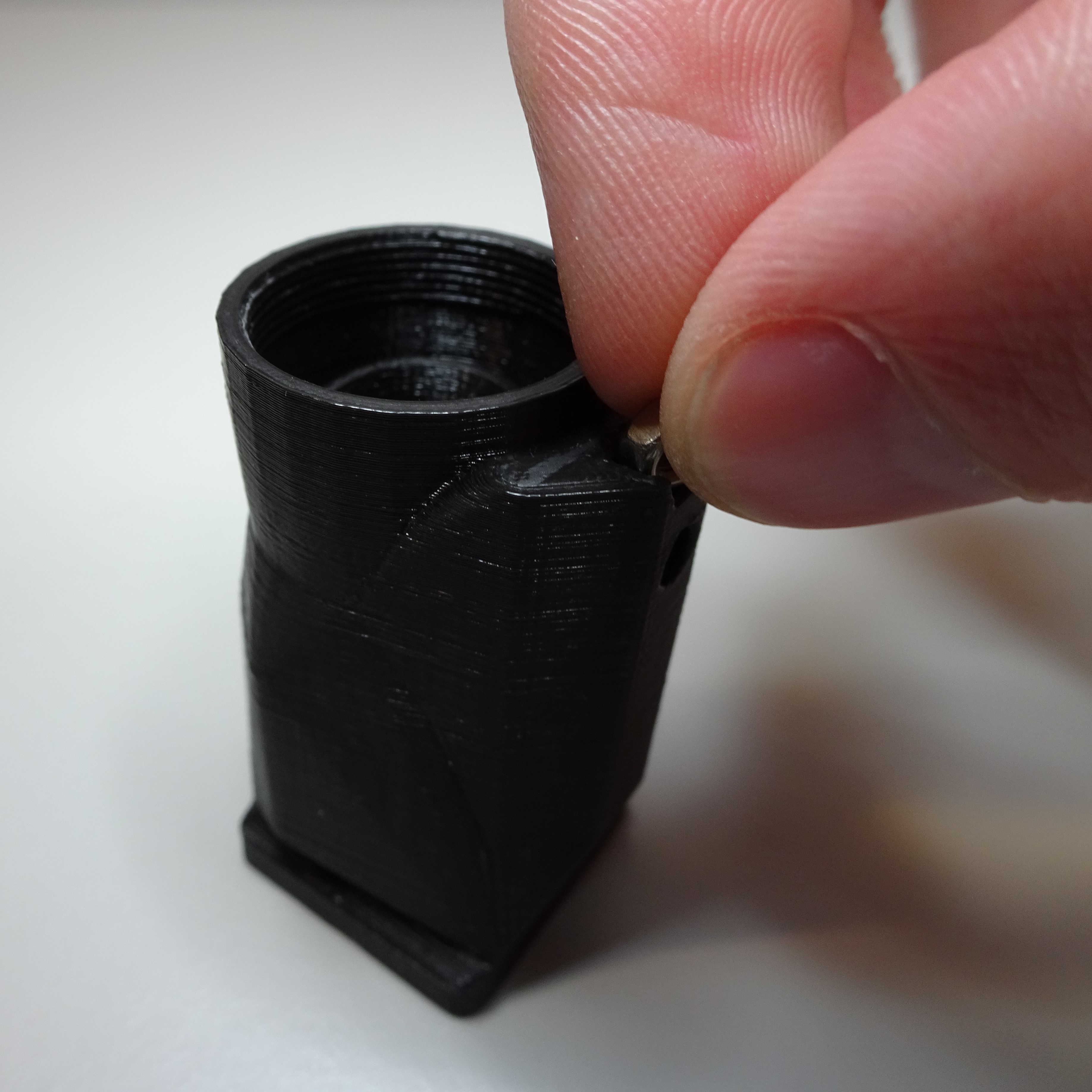

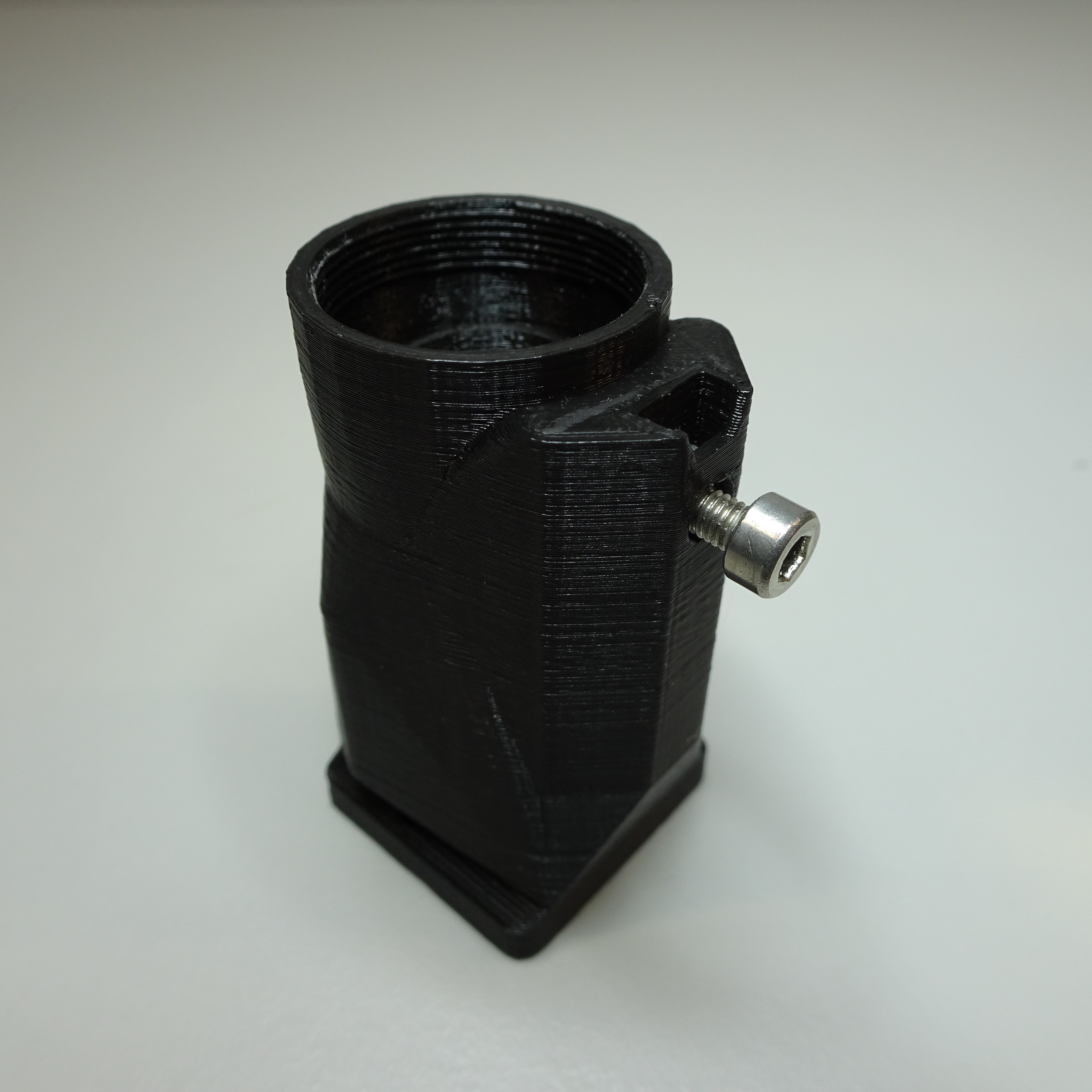

Step 9: Insert the tube lens
Put the tube lens onto the lens tool, with the more convex side down.
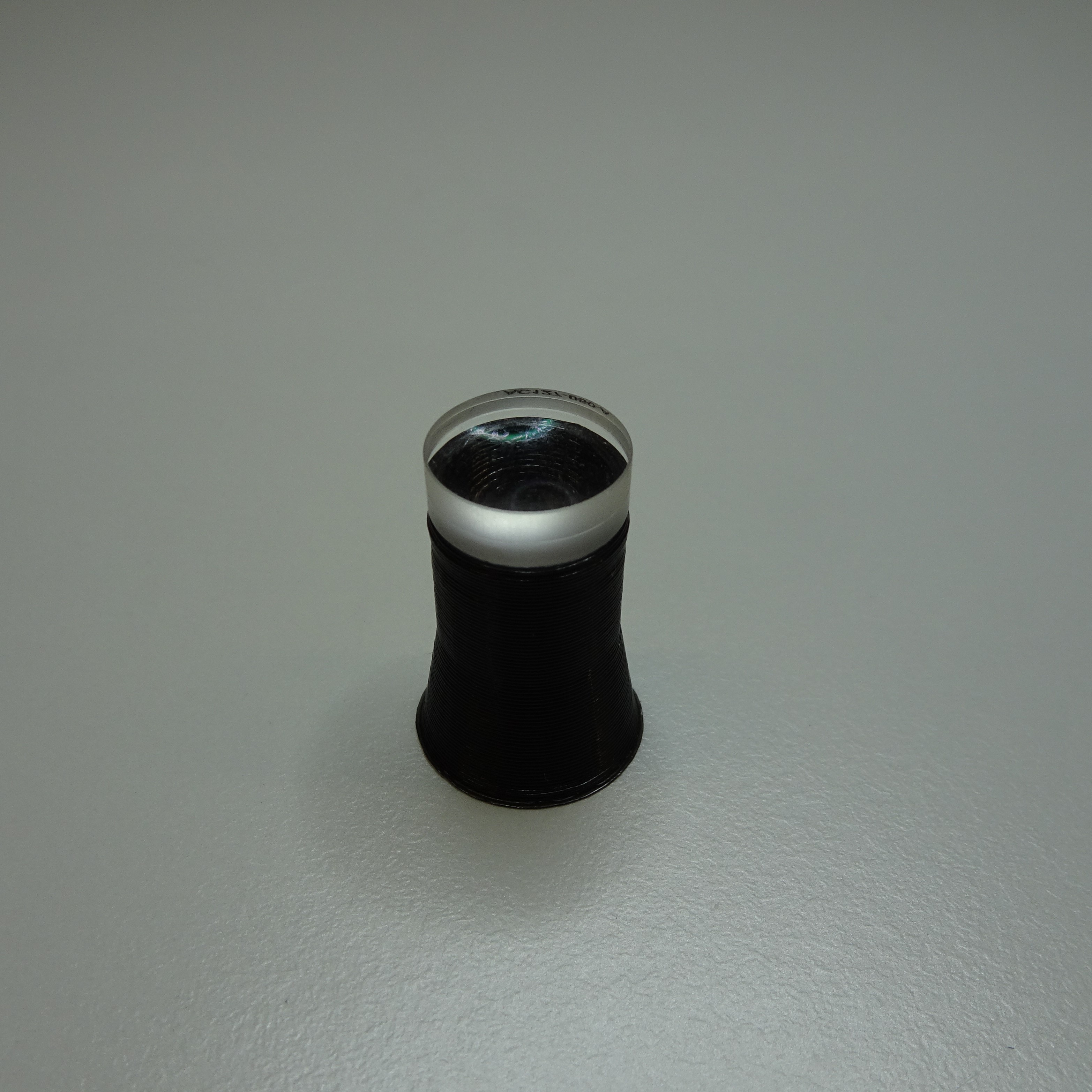
Push the reflection optics module casing down on top of the lens until it is flat and secure.
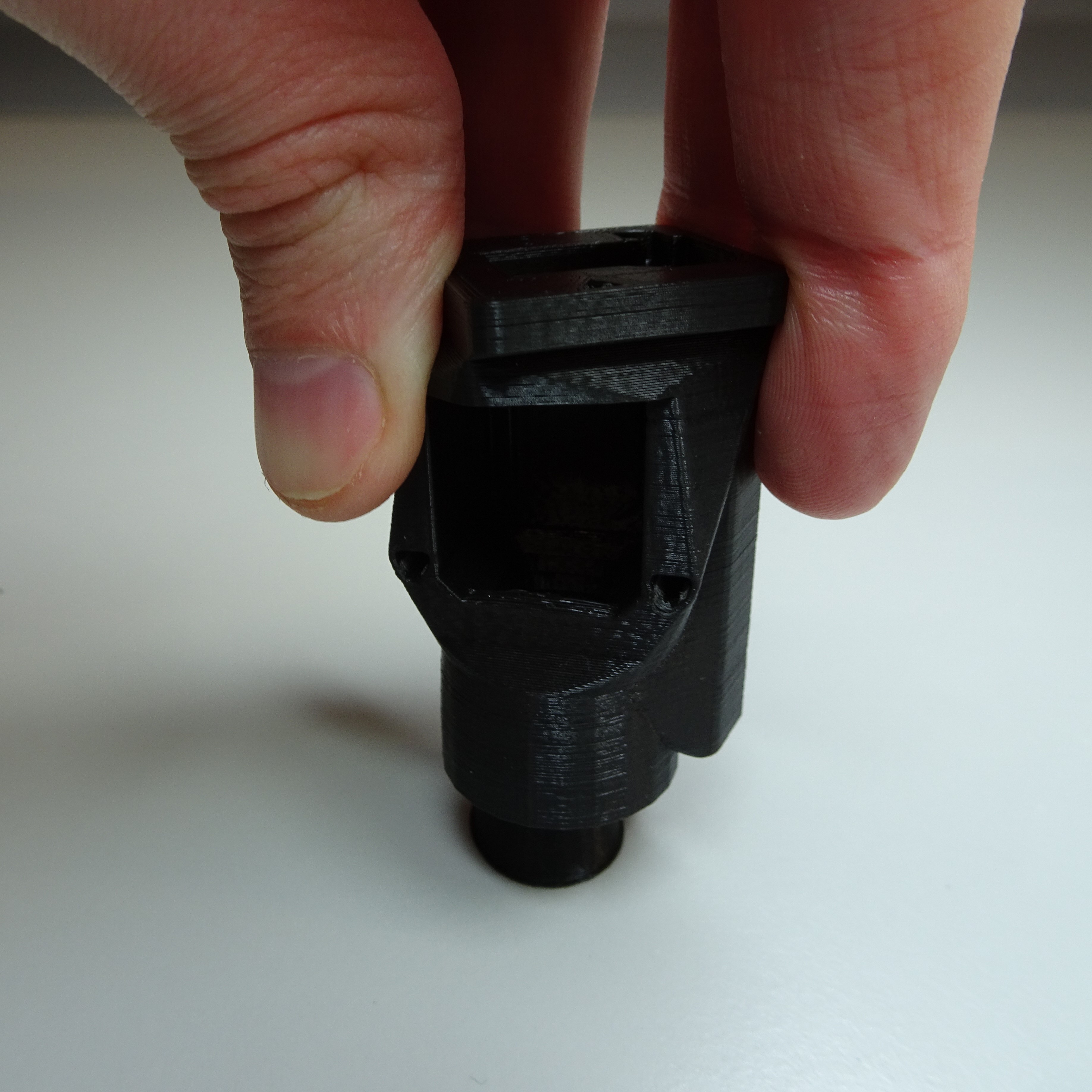
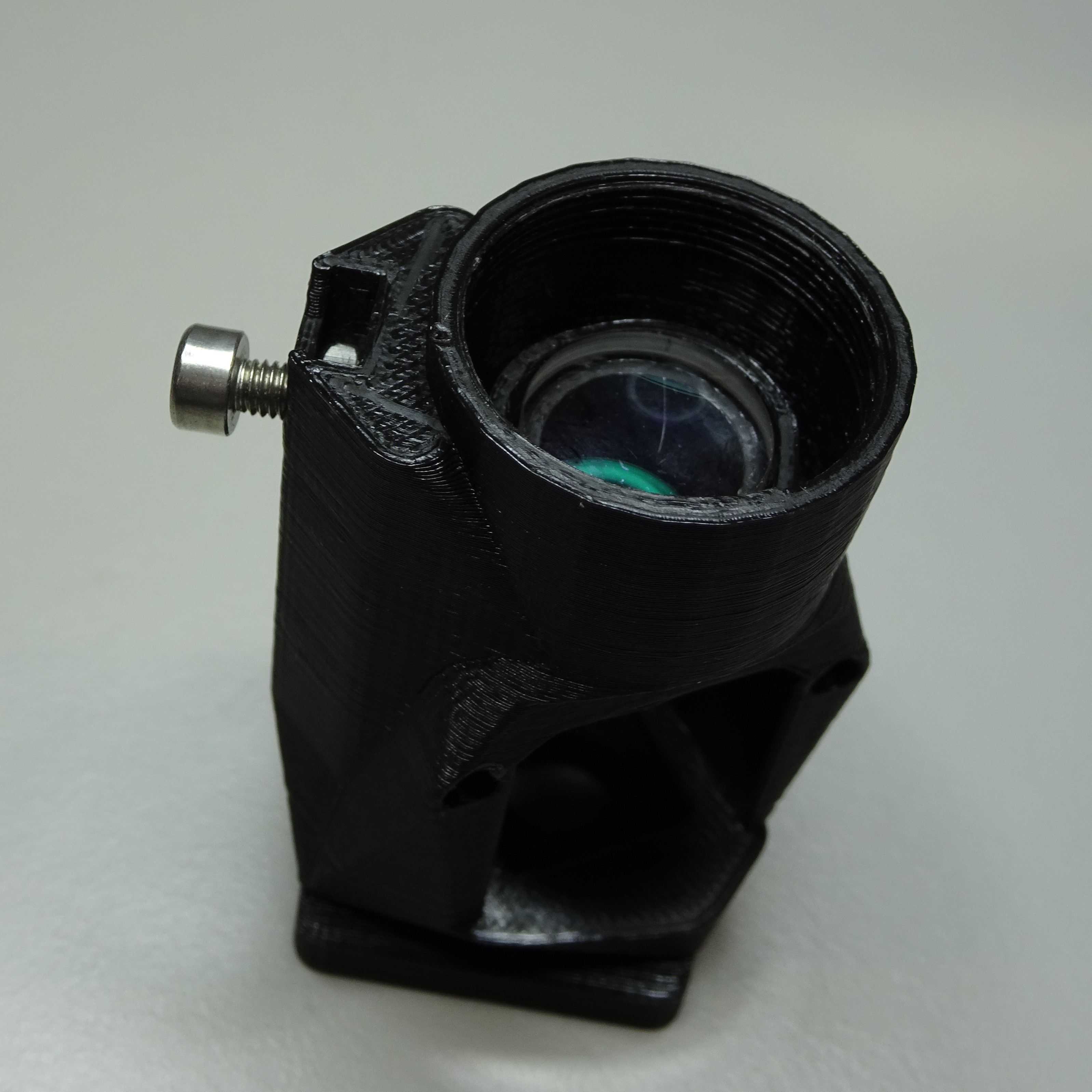

Step 10: Attach the objective lens
Screw the objective lens into the top of the reflection optics module casing. Be careful to screw it in straight, to avoid cross-threading.
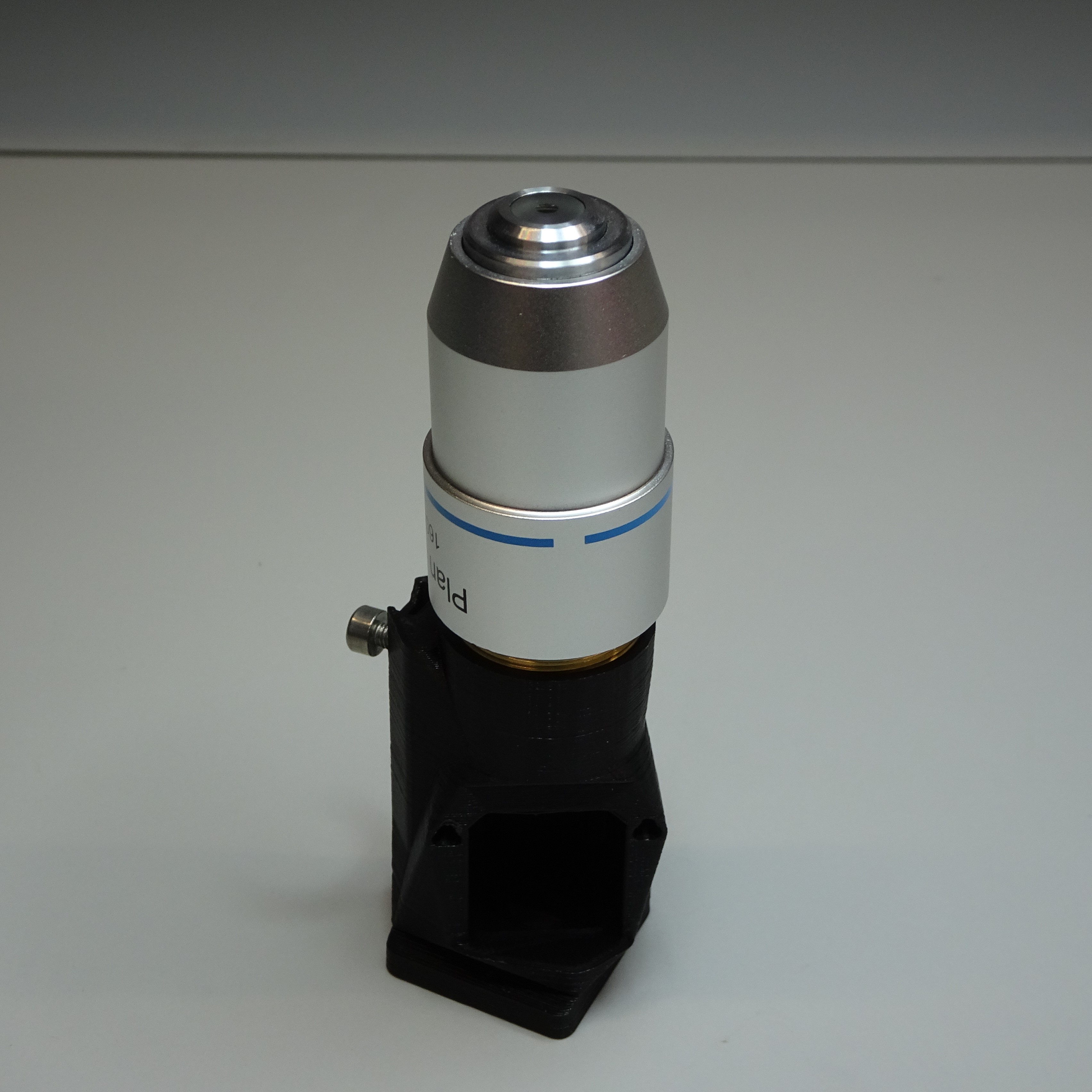
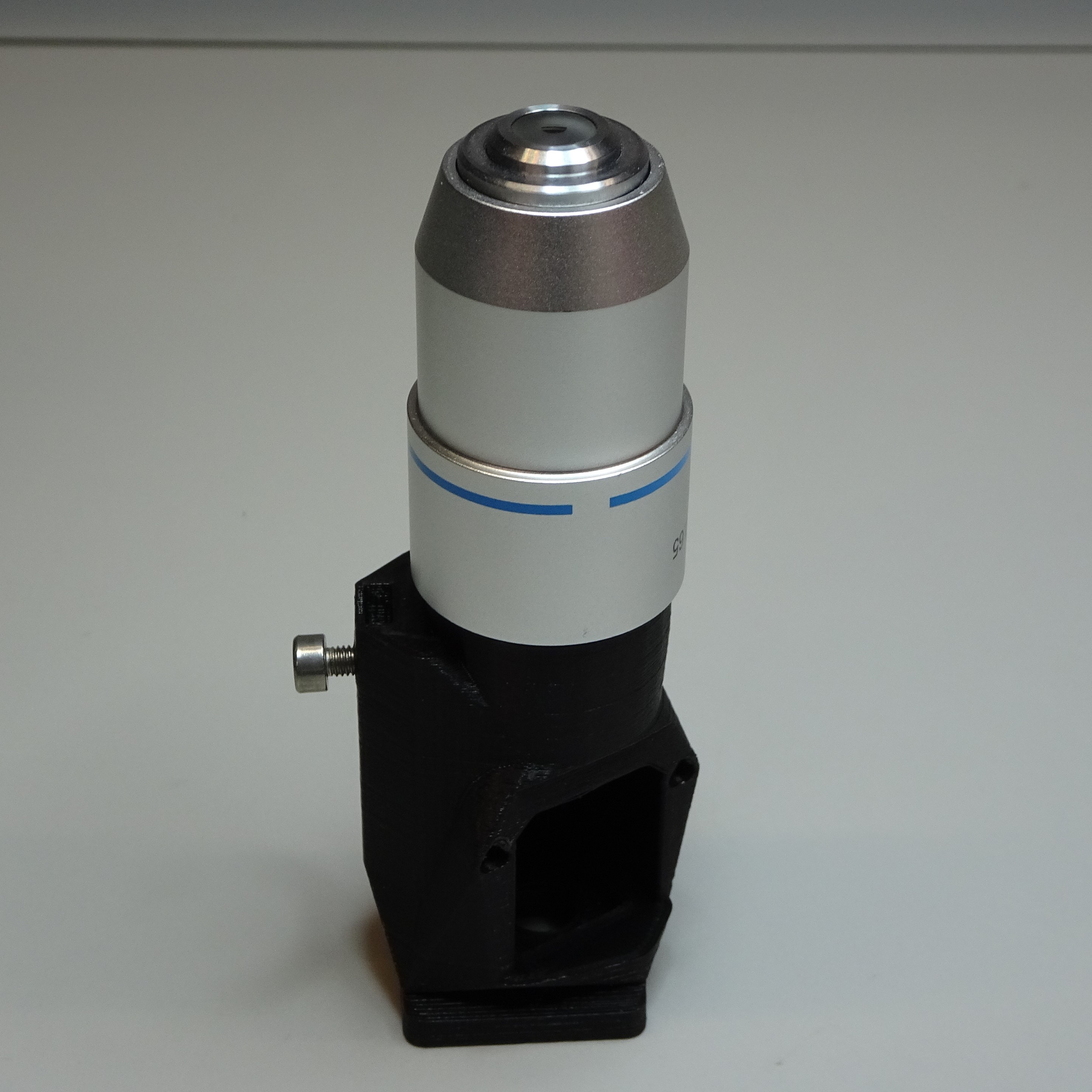

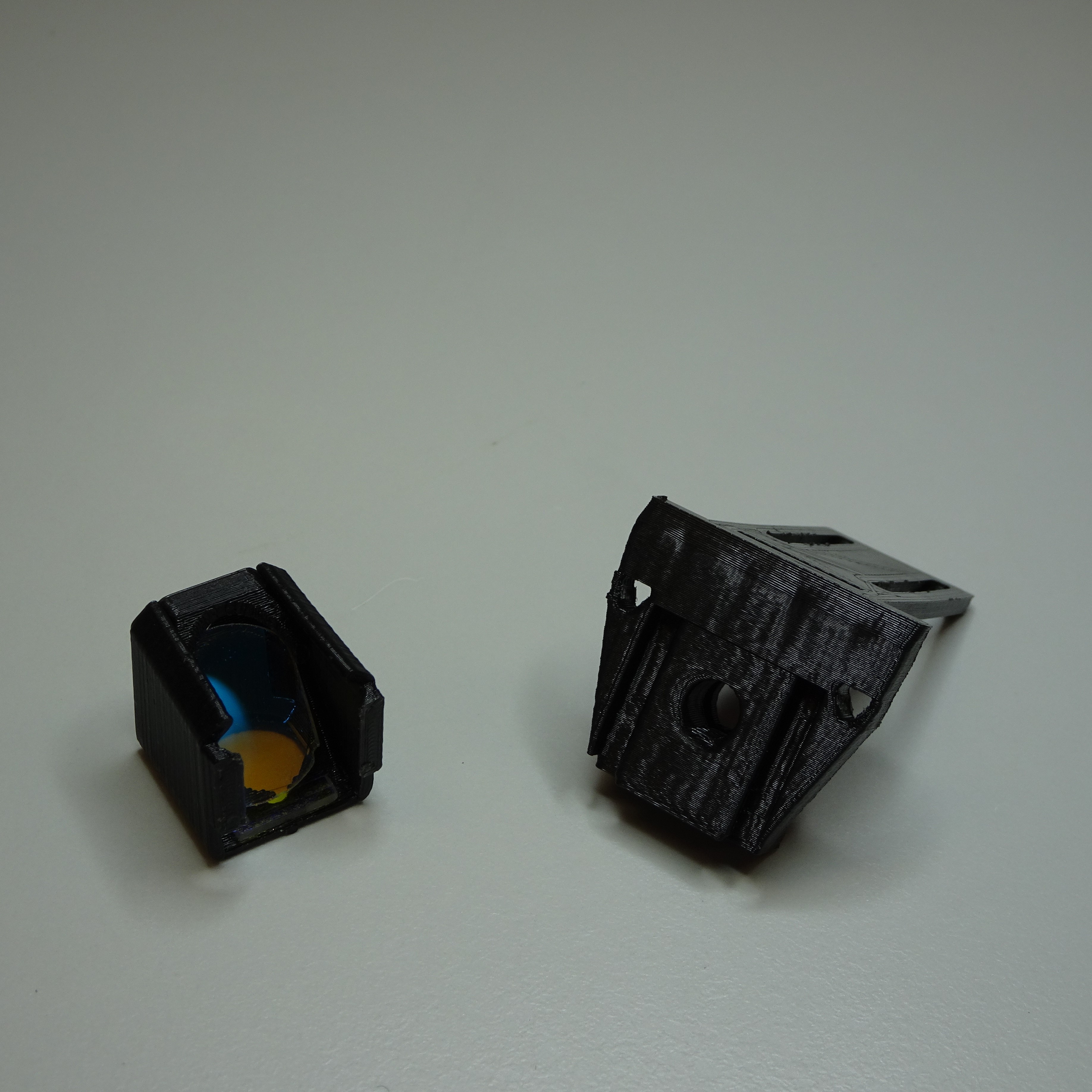
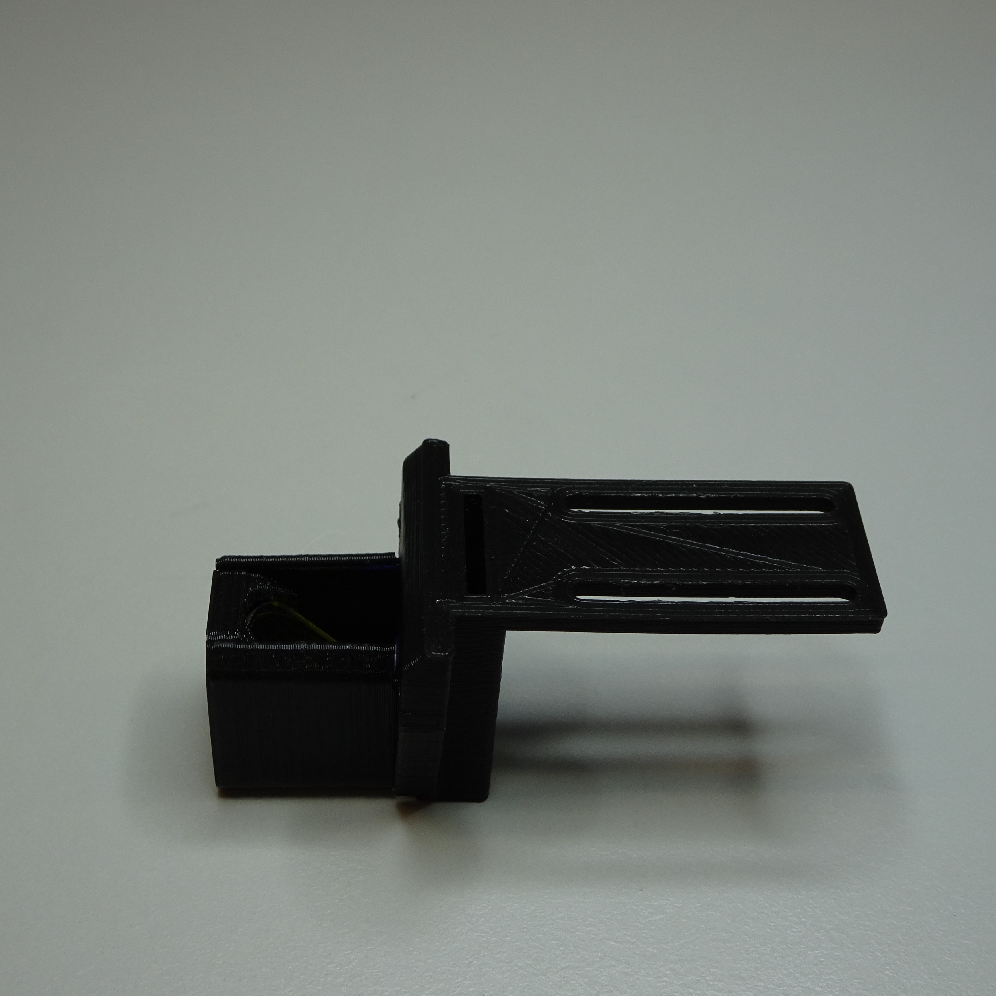
Step 11: Attach the filter cube to the reflection illumination holder
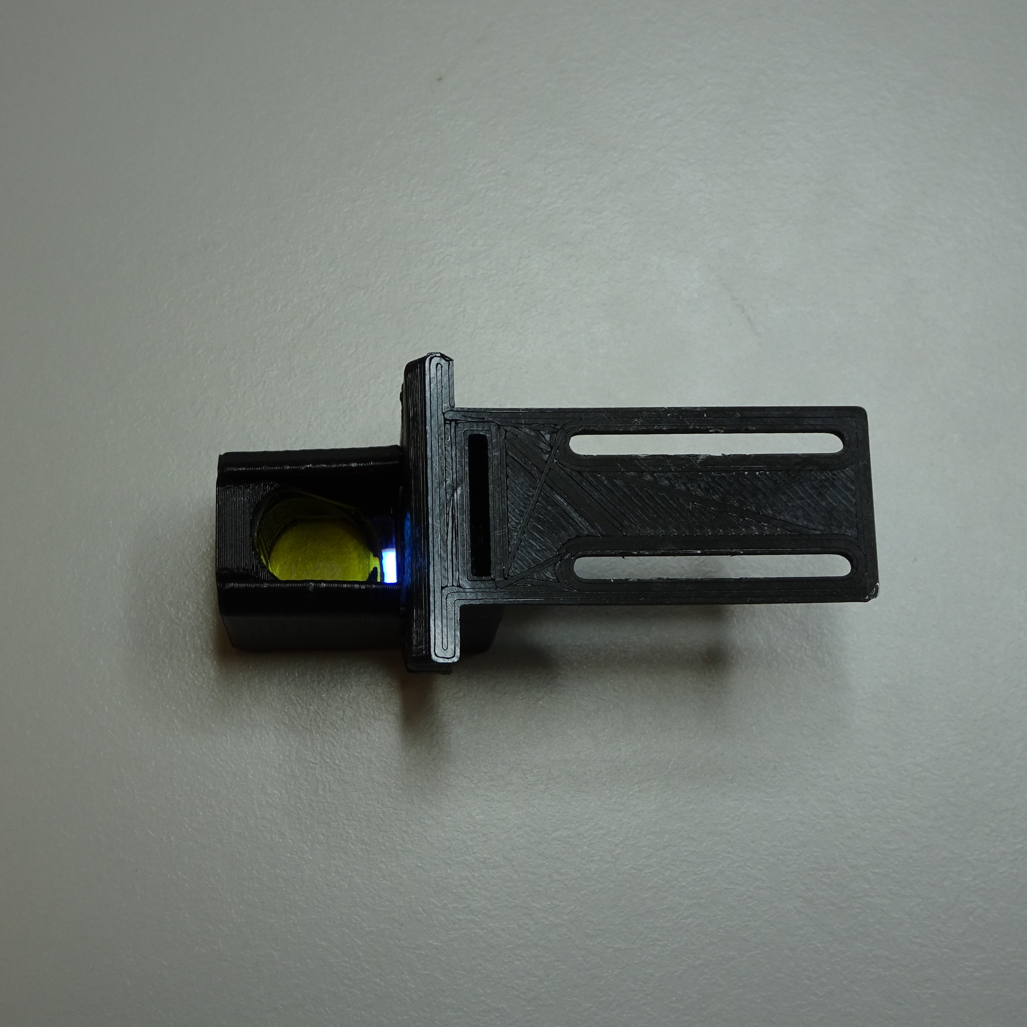
Slide the filter cube into the dovetail of the reflection illumination holder.

Step 12: Insert the excitation filter
The excitation filter slides into the slot on top of the reflection illumination holder.
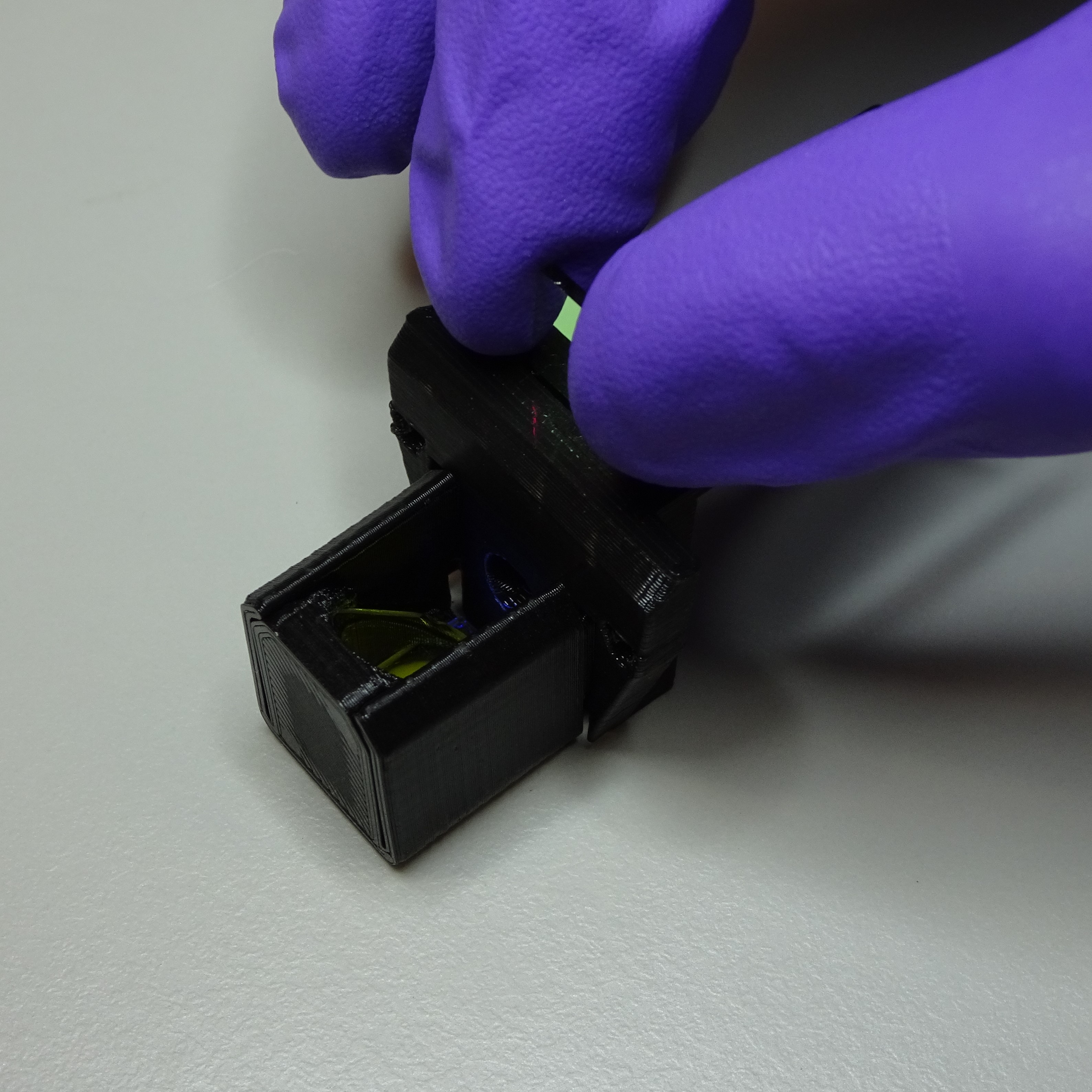
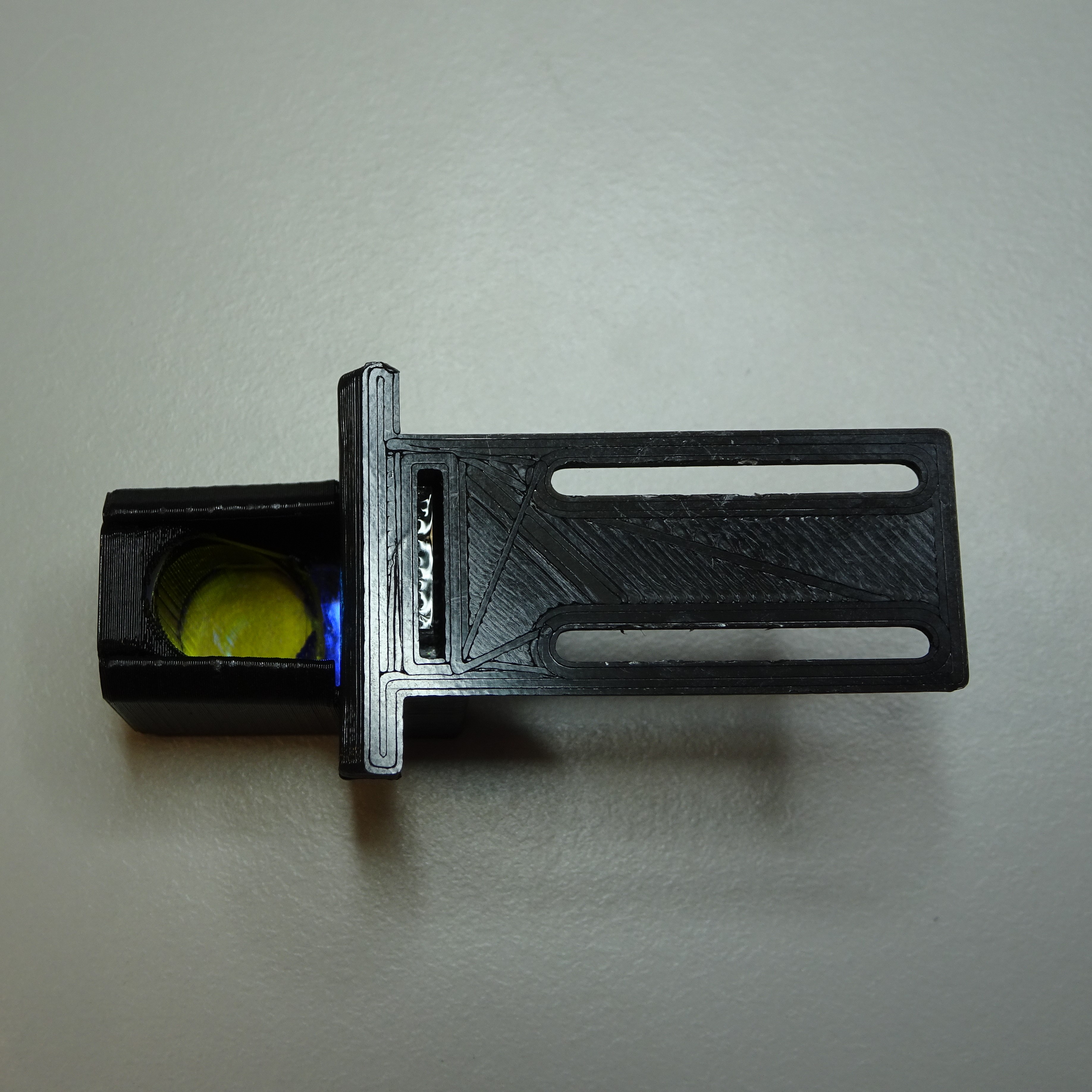

Step 13: Attach the reflection illumination holder to the optics module
Slide the filter cube into the slot in the side of the reflection optics module casing.
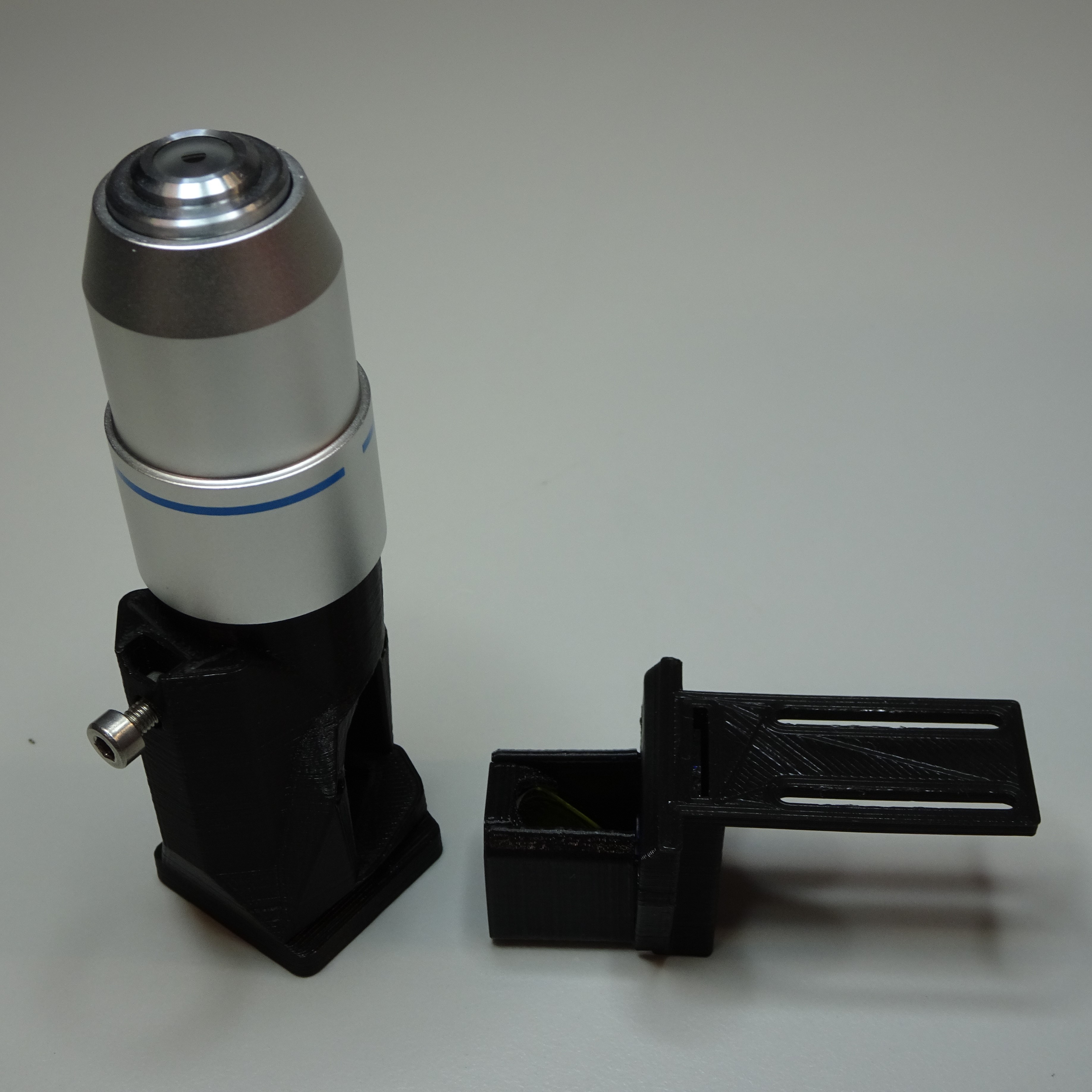
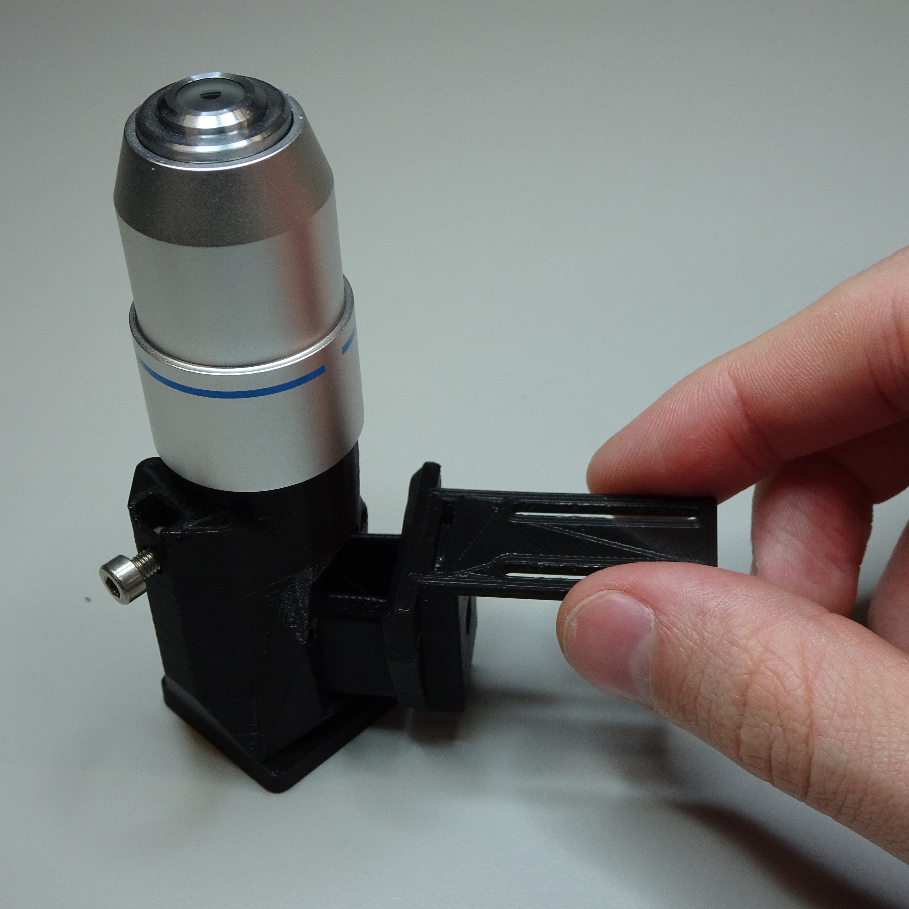


Screw the reflection illumination holder to the reflection optics module casing using two M2.5x8mm screws.
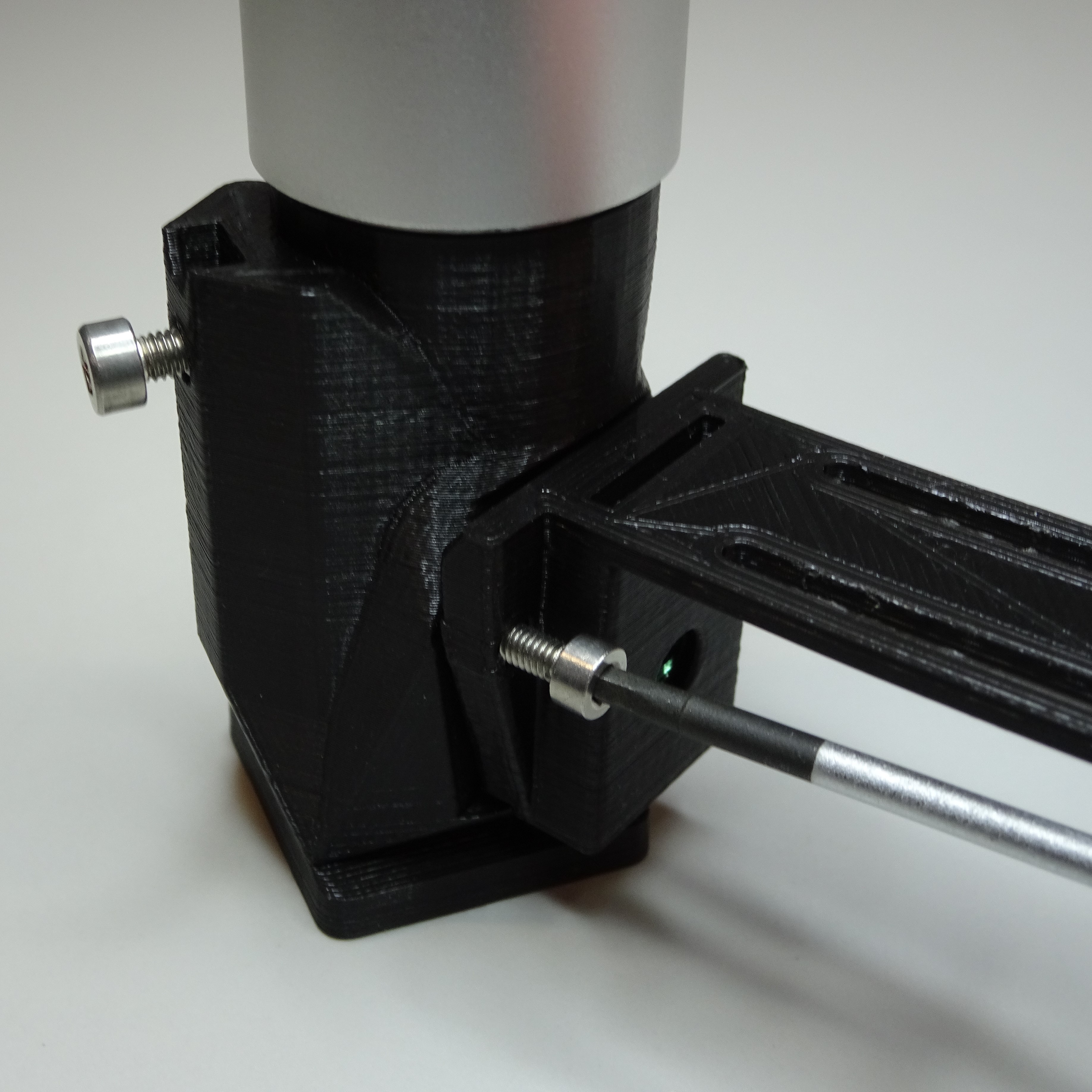
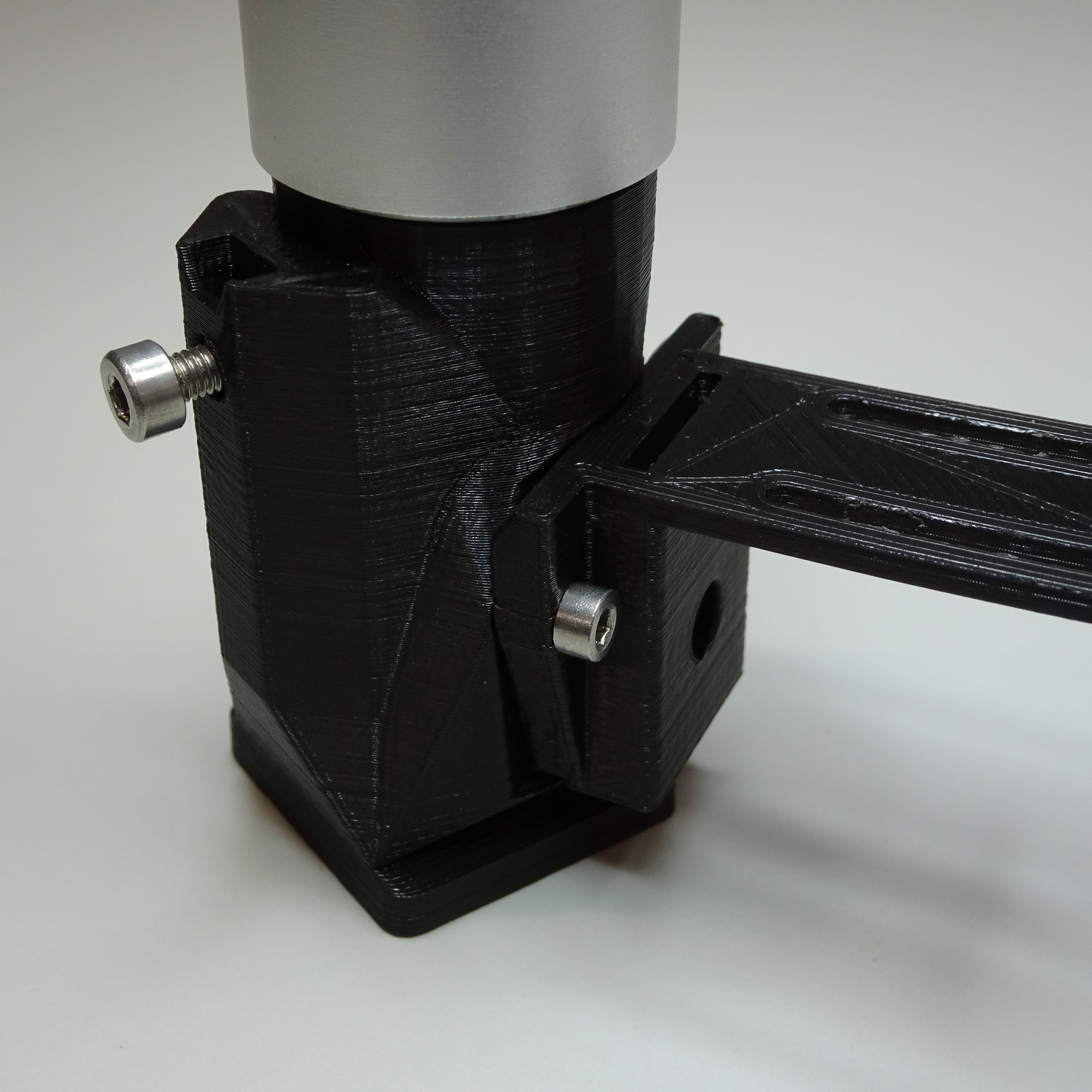
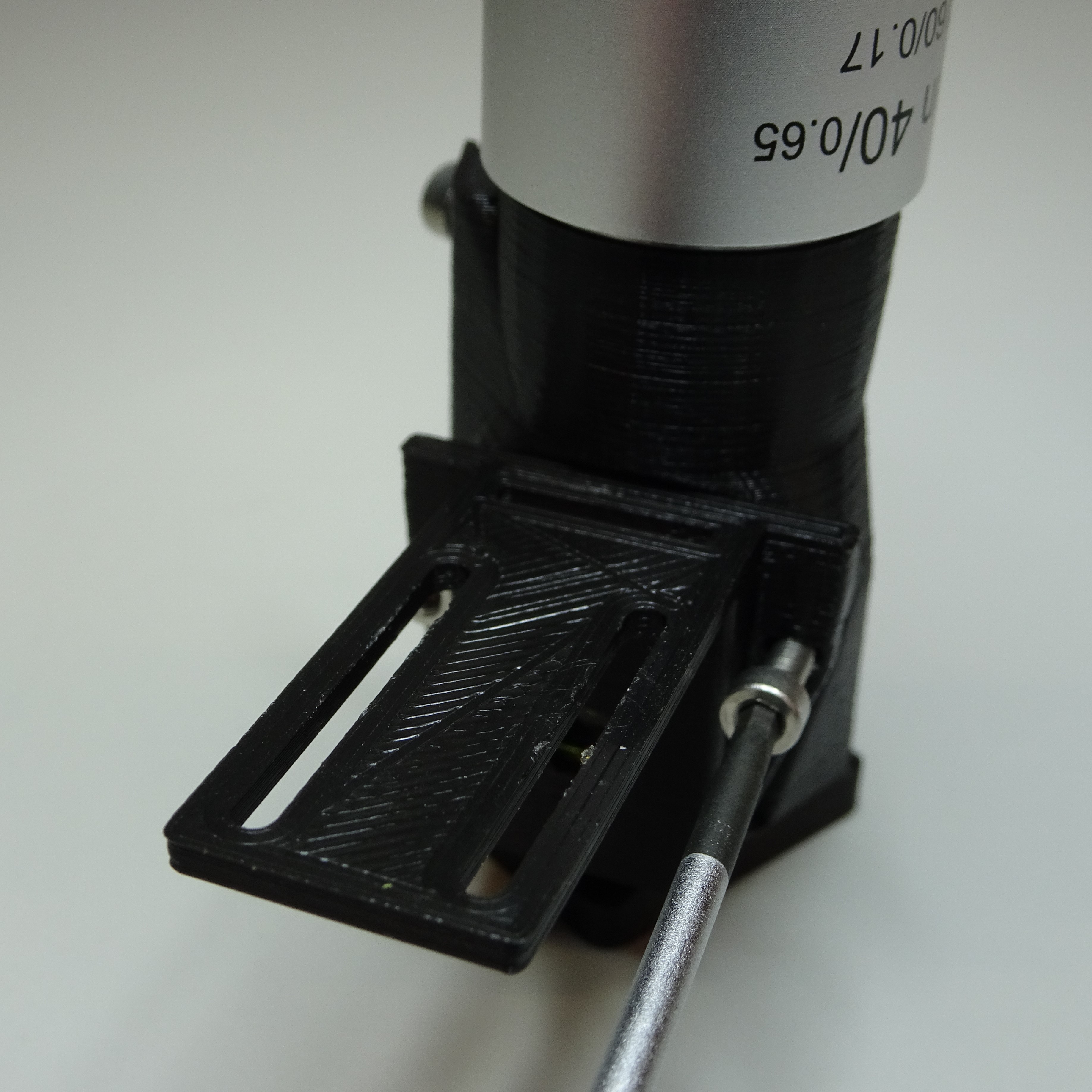
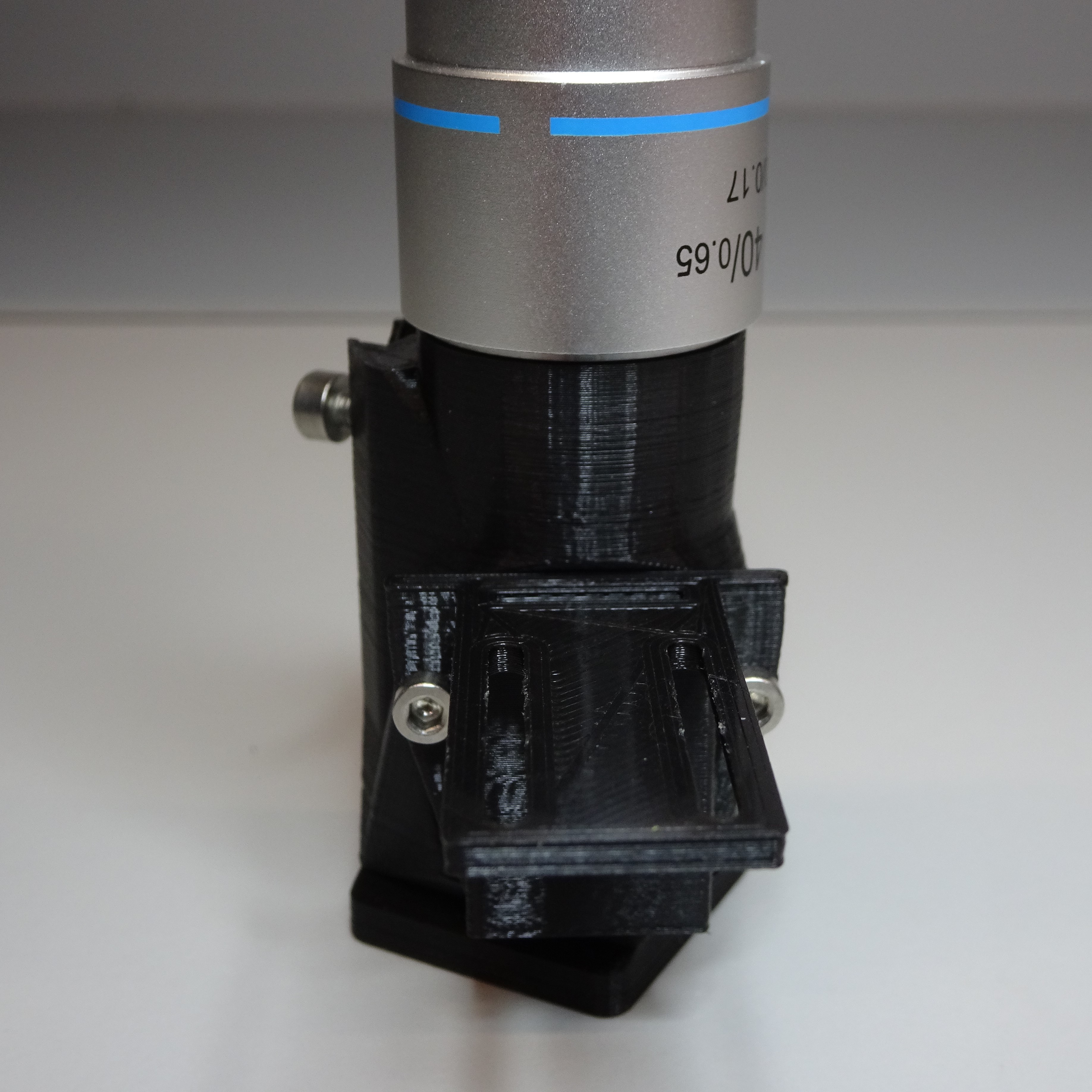

Secure the excitation filter
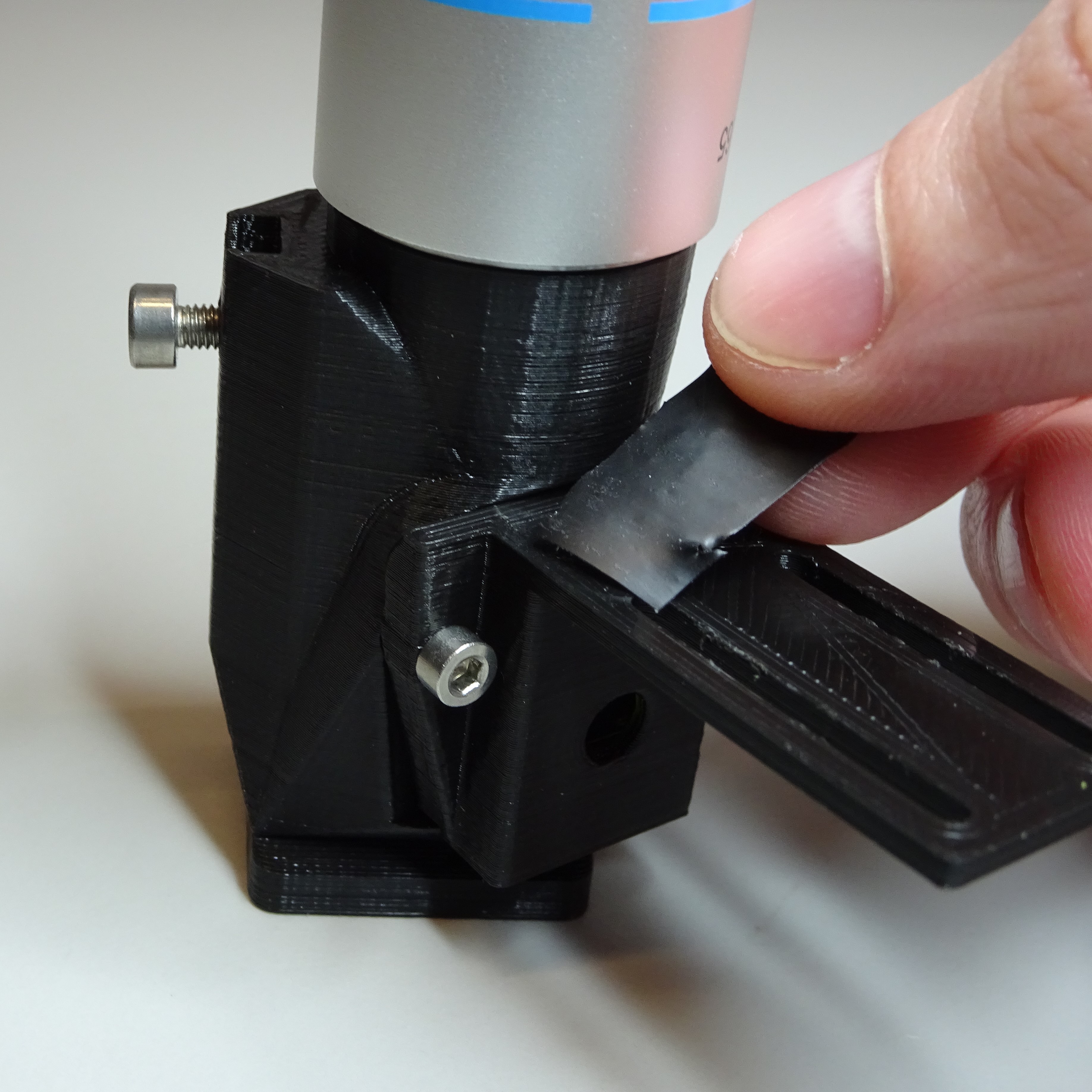
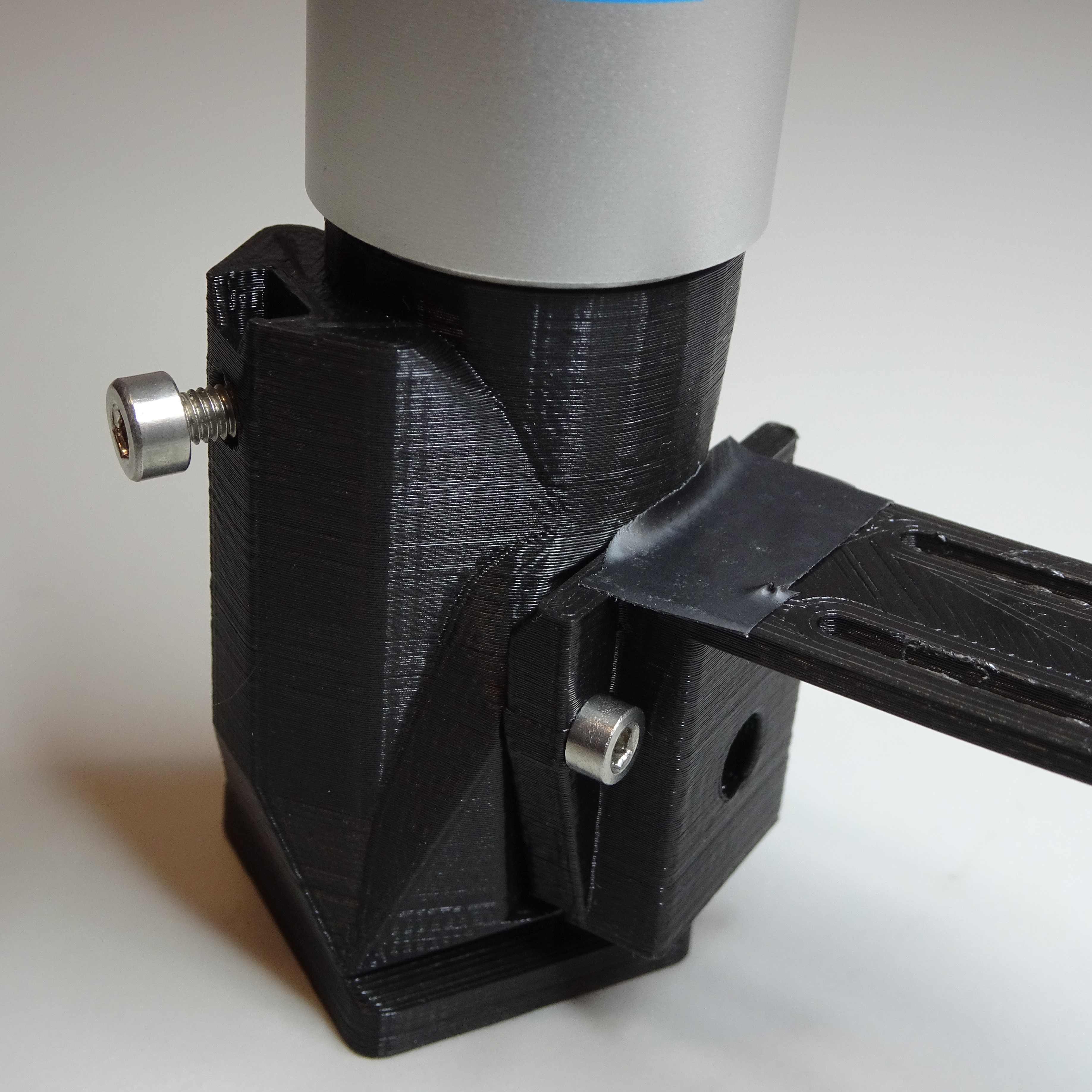
Put some electrical tape over the excitation filter slot to keep the excitation filter in place.

Attach the reflection illumination holder
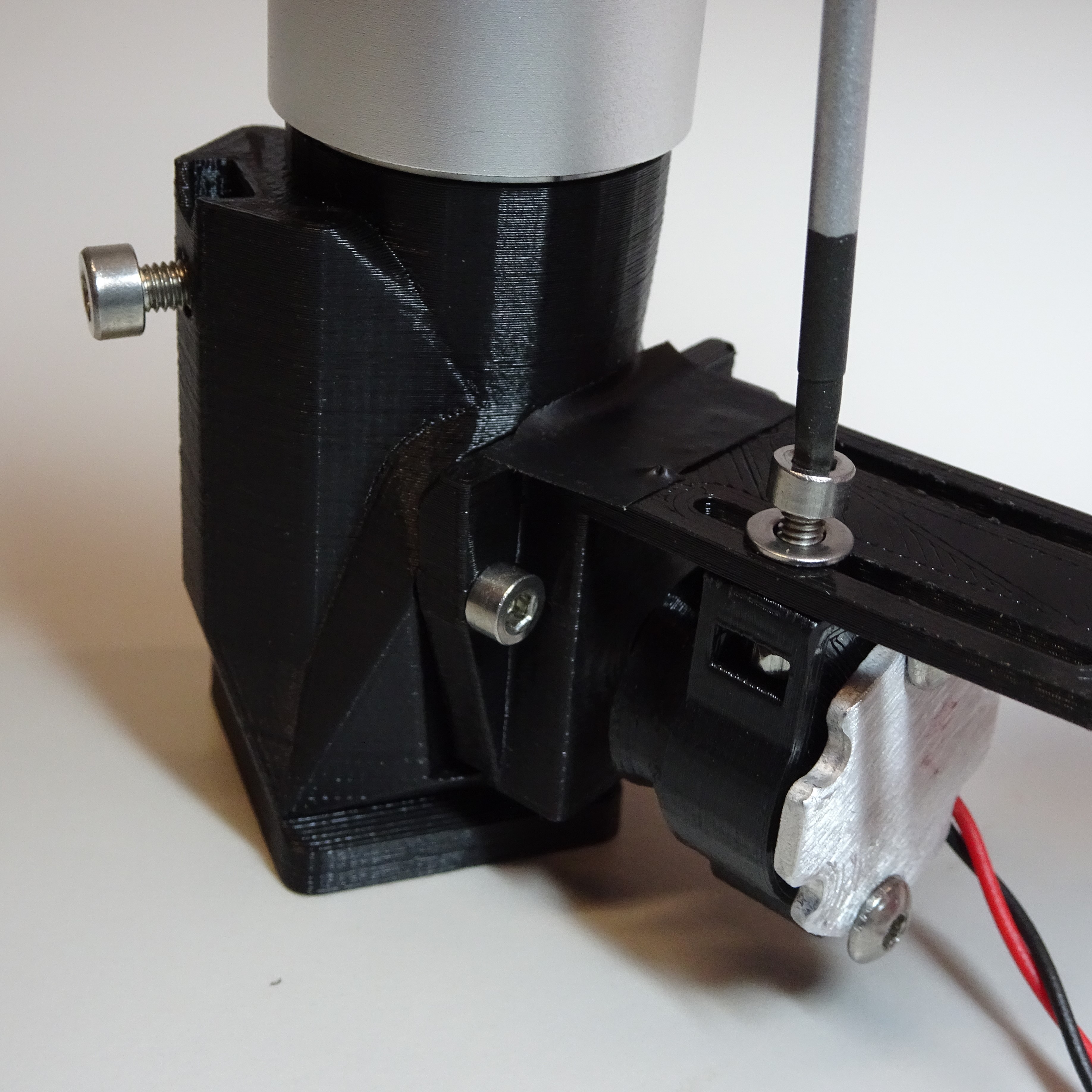
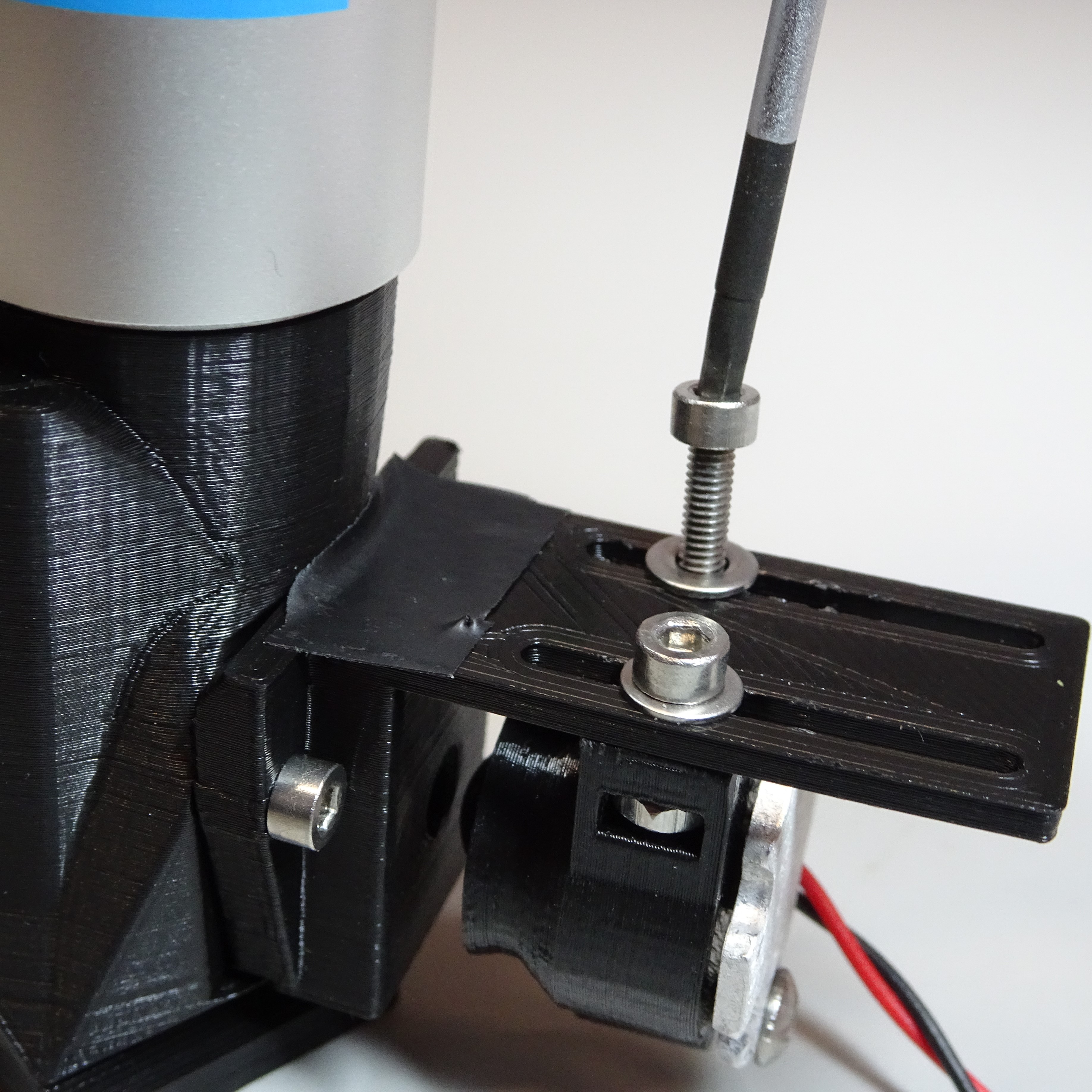
Put two M2.5 washers onto two M2.5x8mm screws. Screw through the slip plate on the reflection illumination holder into the M2.5 nut in the reflection illumination condenser using a 2mm hex screwdriver.
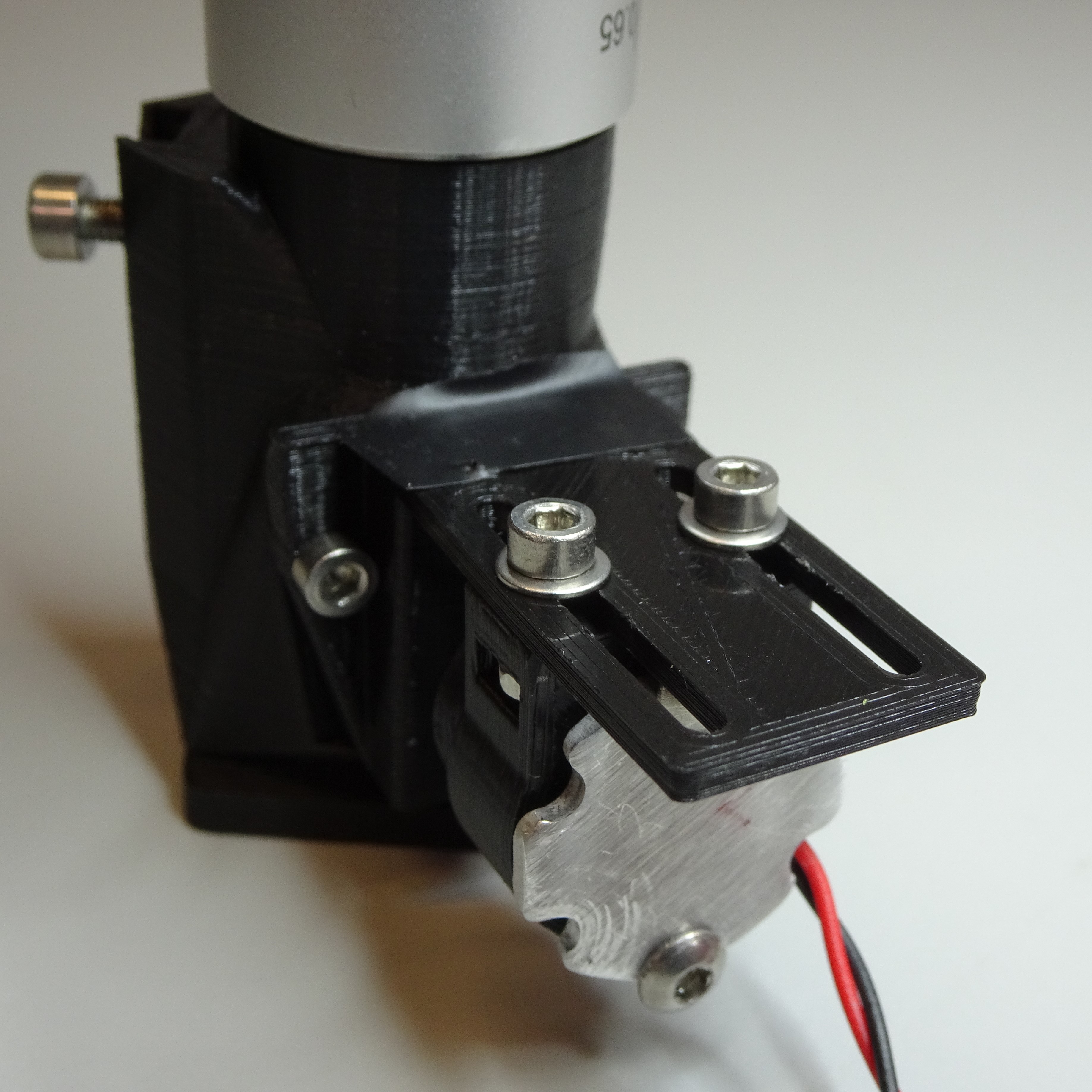

Step 14: Remove the camera lens
Remove the plastic film from the lens of the Raspberry Pi camera v2.
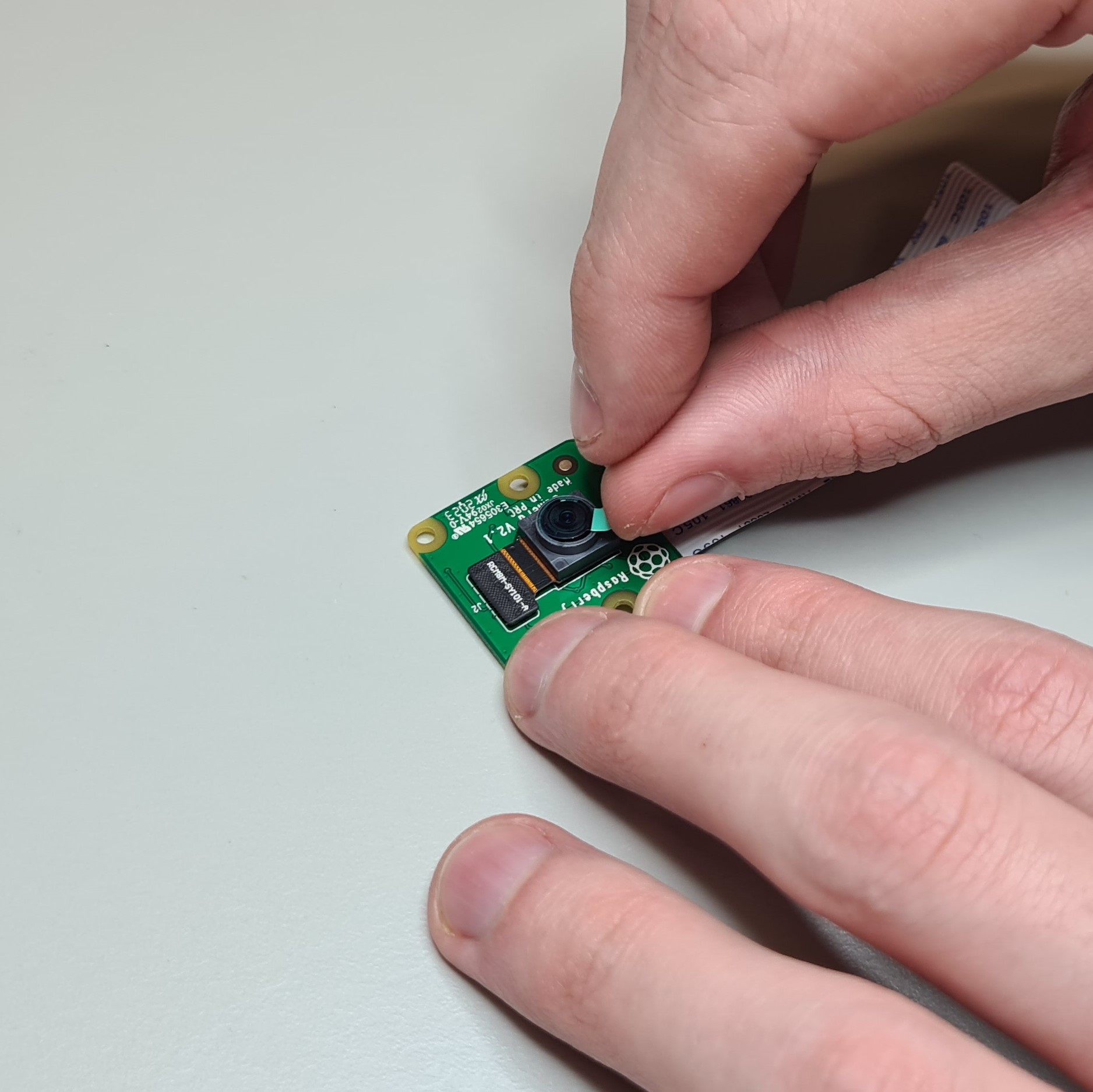
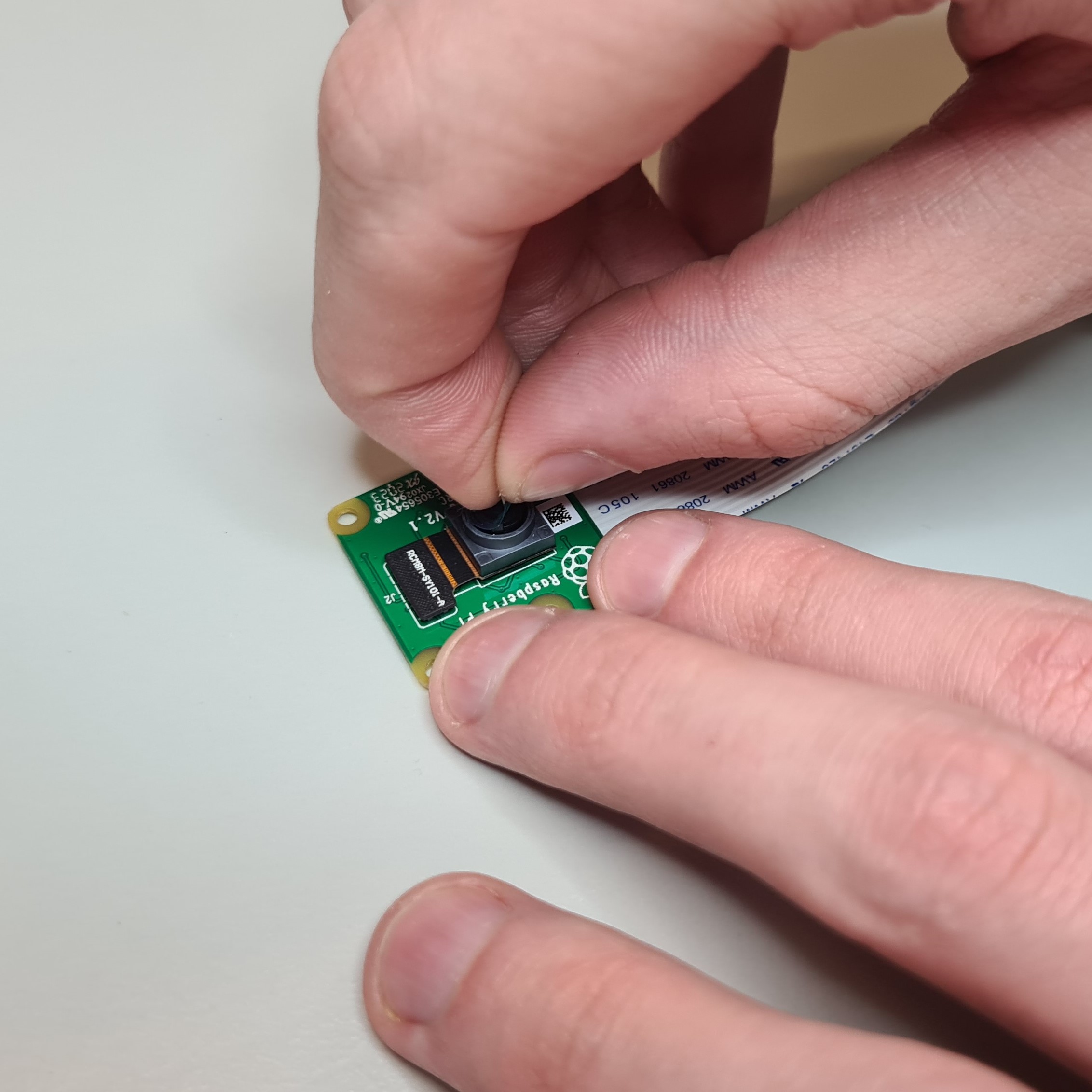

Unscrew the camera lens using the camera lens tool supplied with the camera.
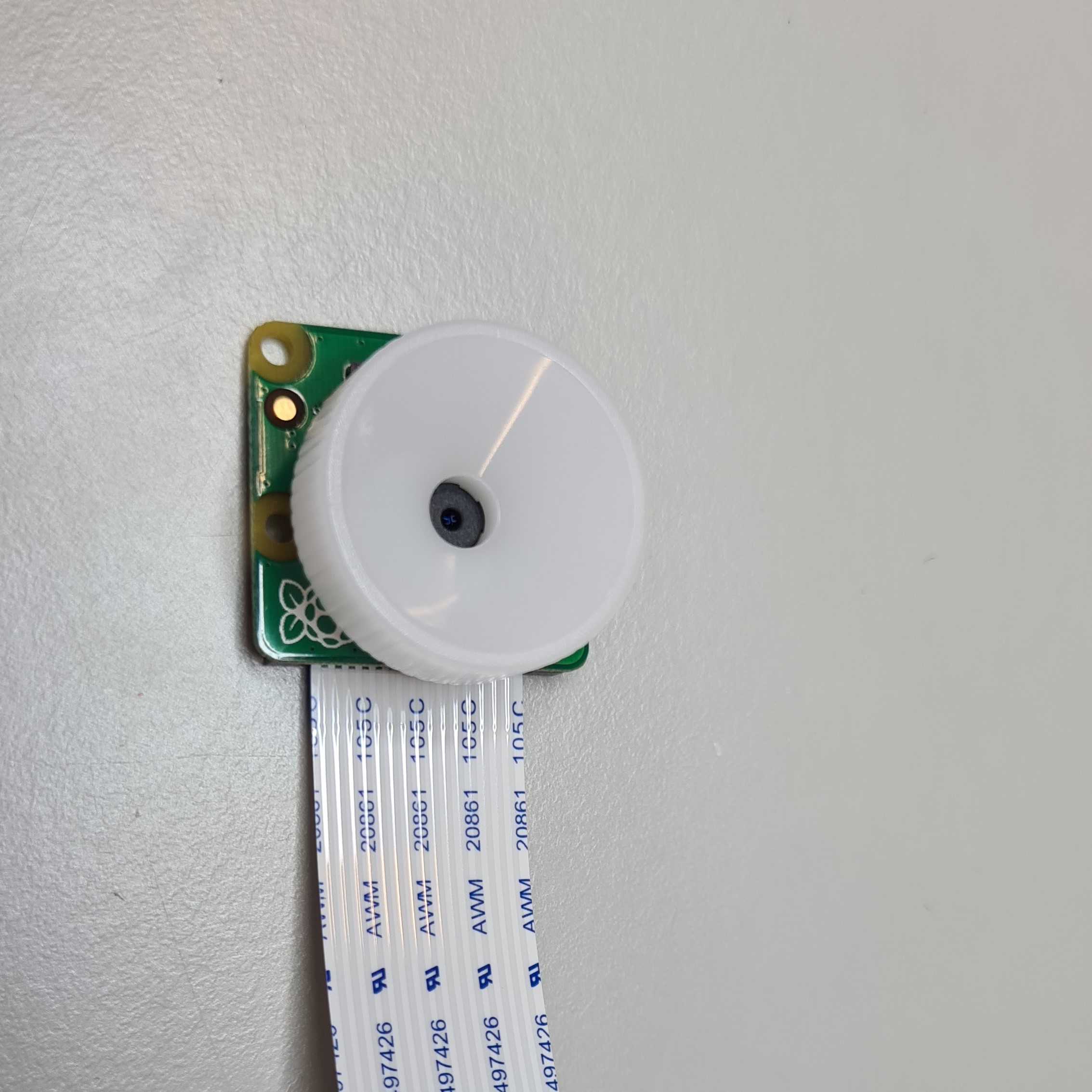
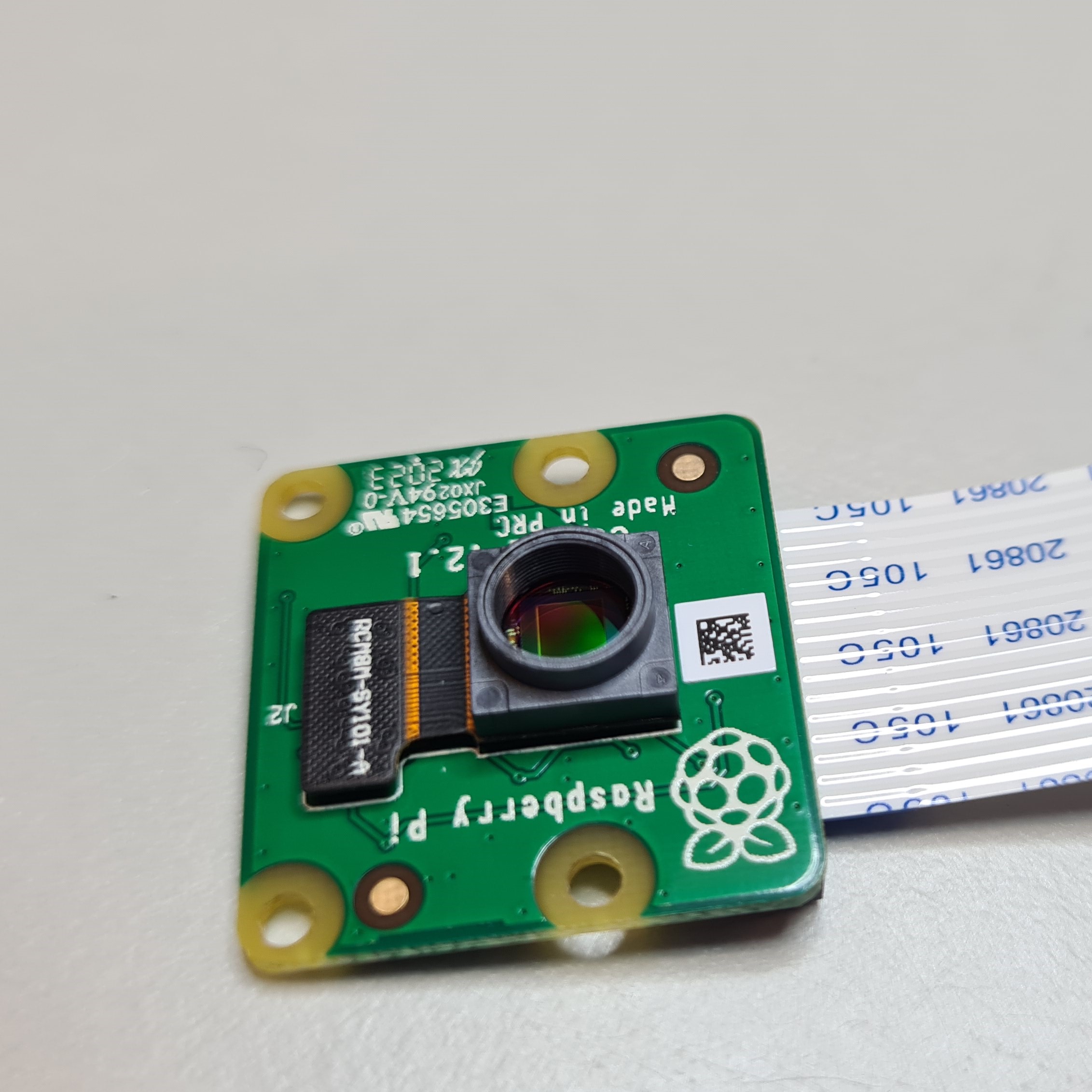

Once you've removed the lens, keep the camera face down or put some tape over the lens holder to stop dust settling on the sensor (which is difficult to clean!).
Step 15: Attach the camera to the optics tube
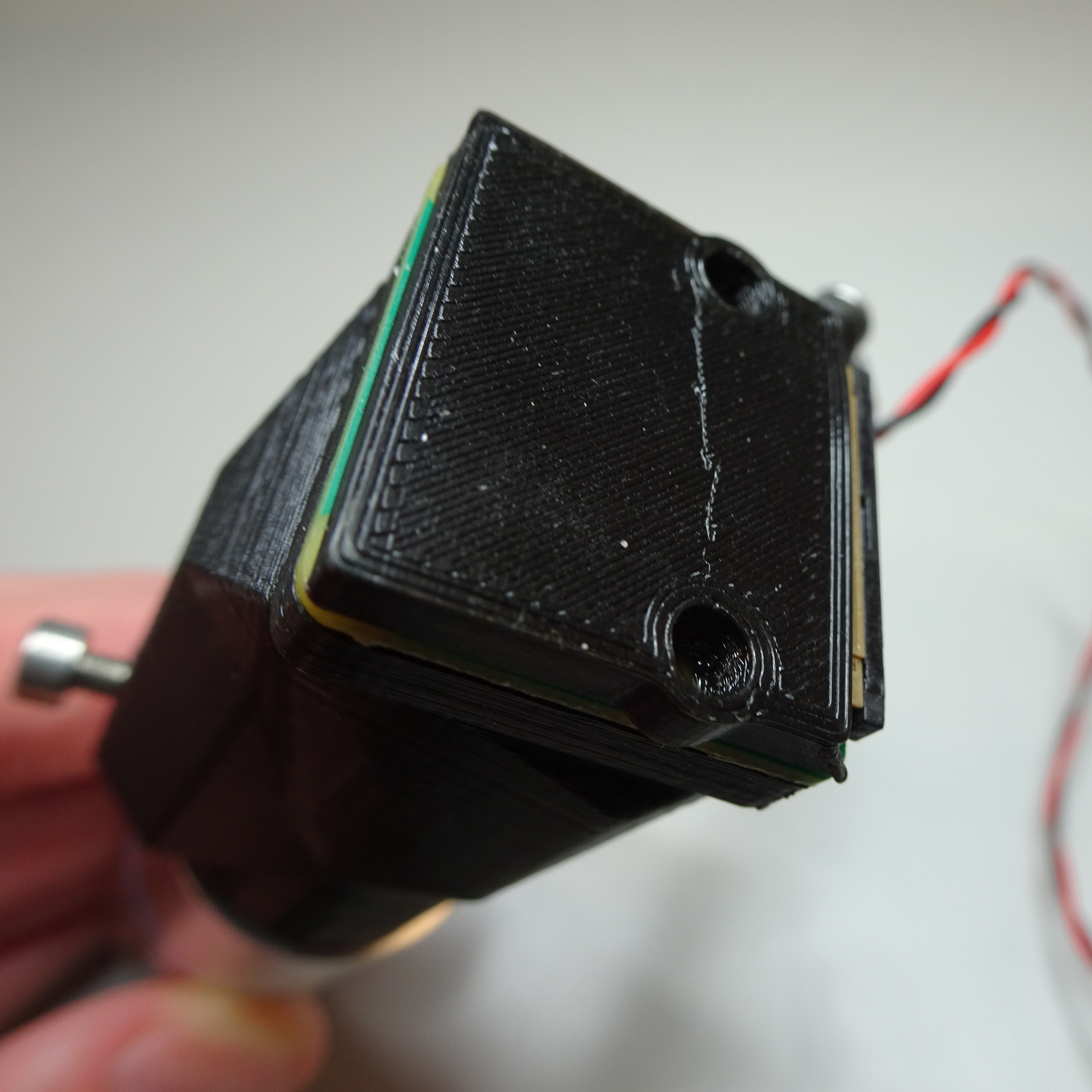
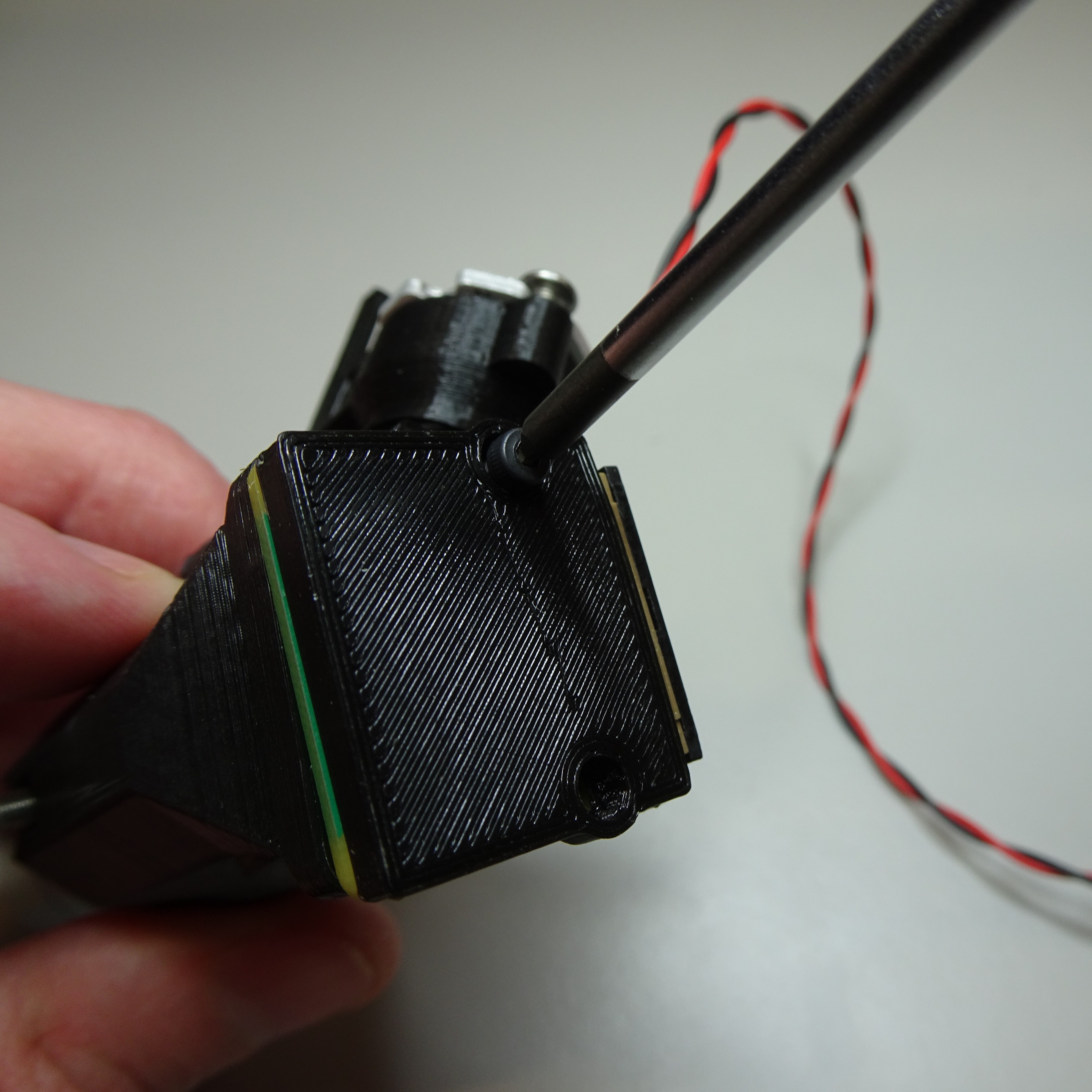
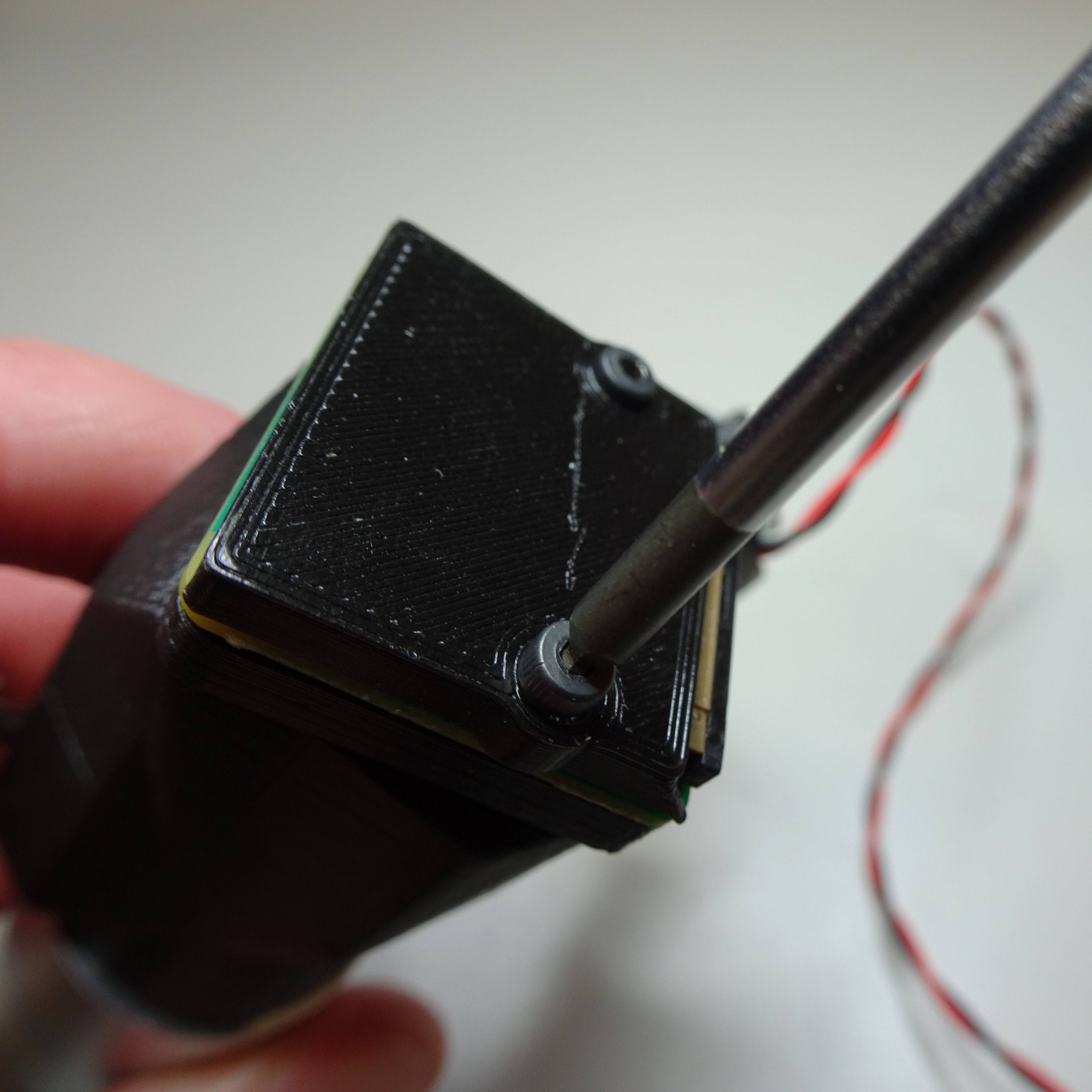
Attach the Raspberry Pi camera v2 to the bottom of the reflection optics module casing. Put the camera cover over the top. Secure everything in place with two M2x6mm screws using a 1.5mm hex screwdriver.


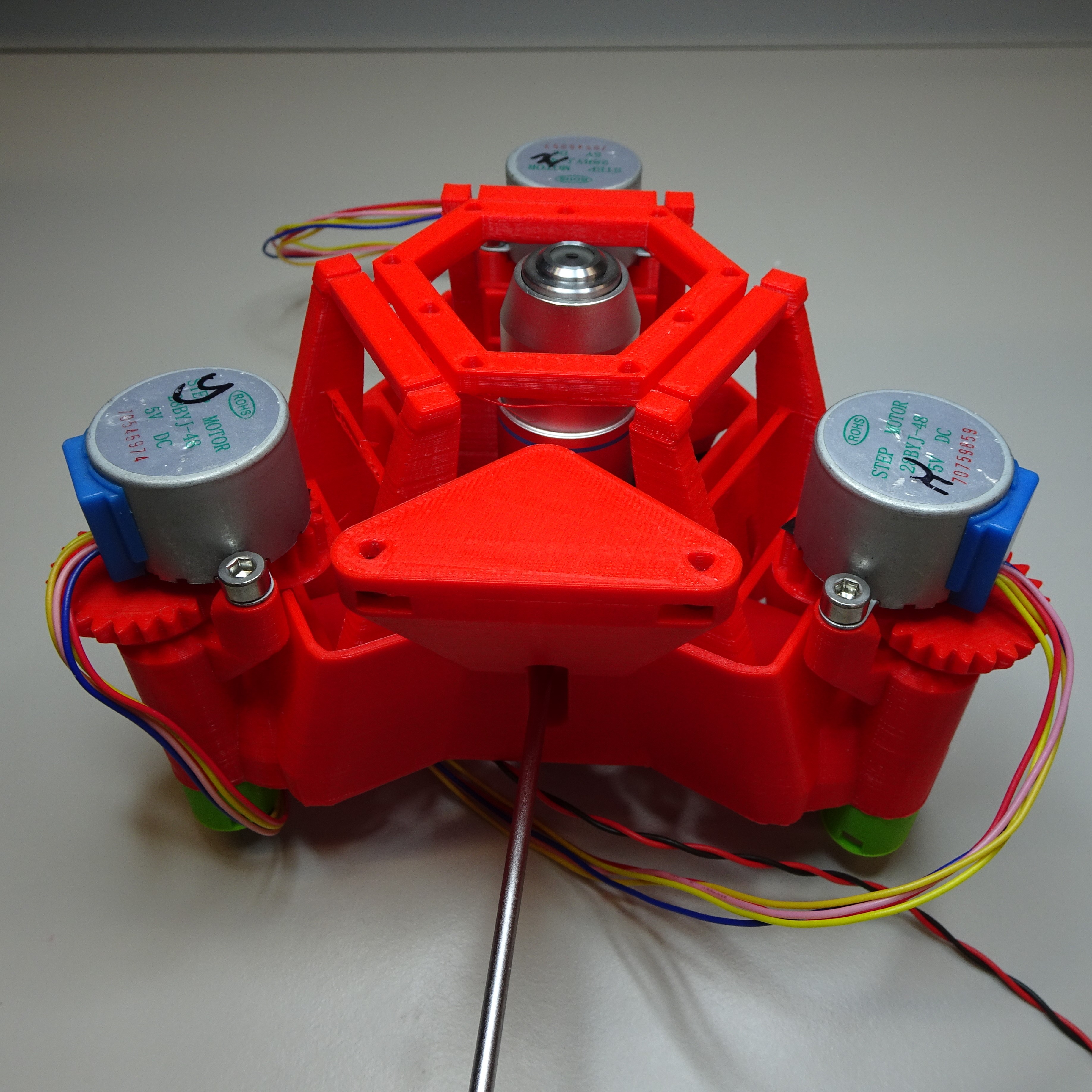
Step 16: Attach the optics module to the Delta Stage
Slot the objective screw into the mount inside the main body.
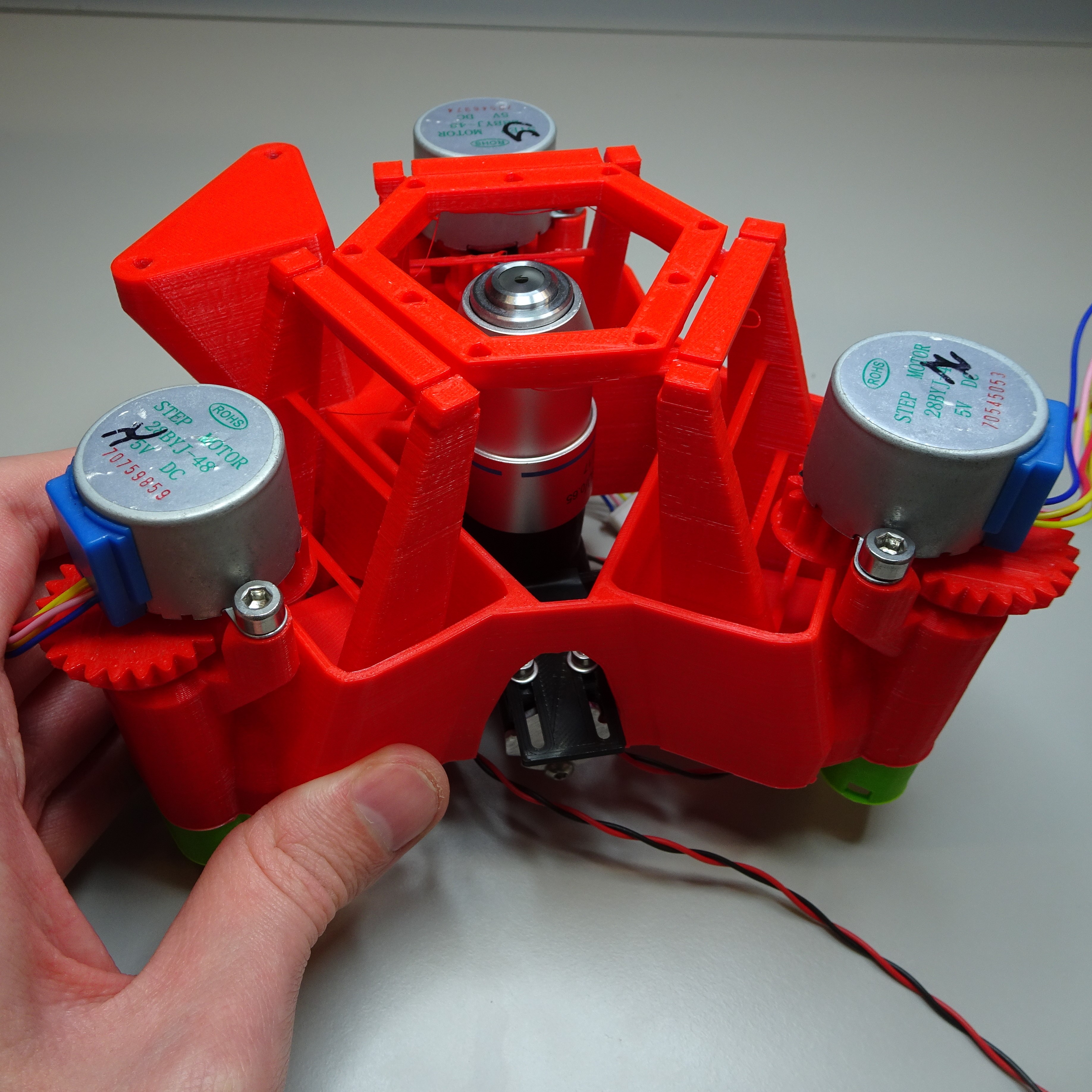
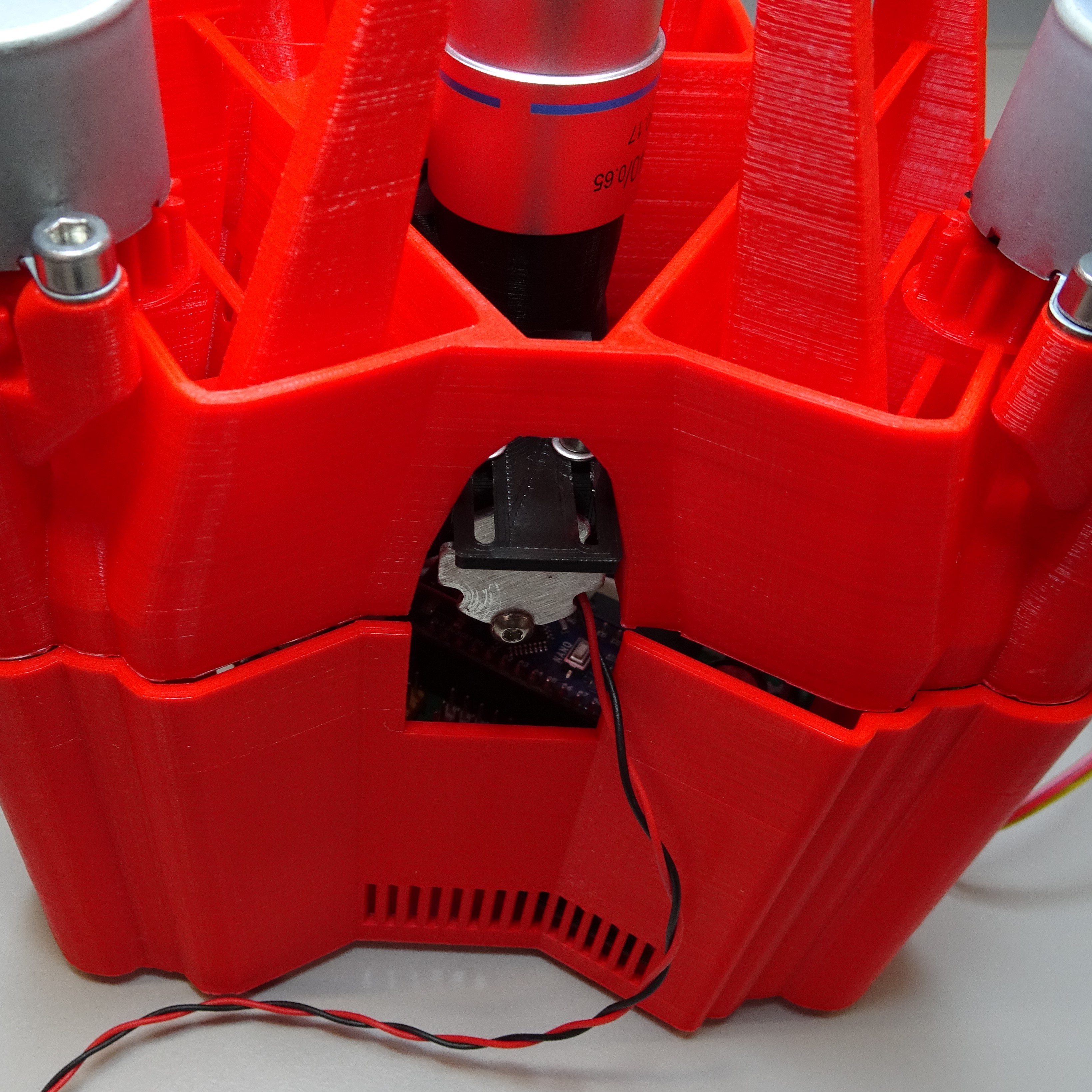
When the optics module is in roughly the correct position, the objective screw can be tightened through the access hole in the back.

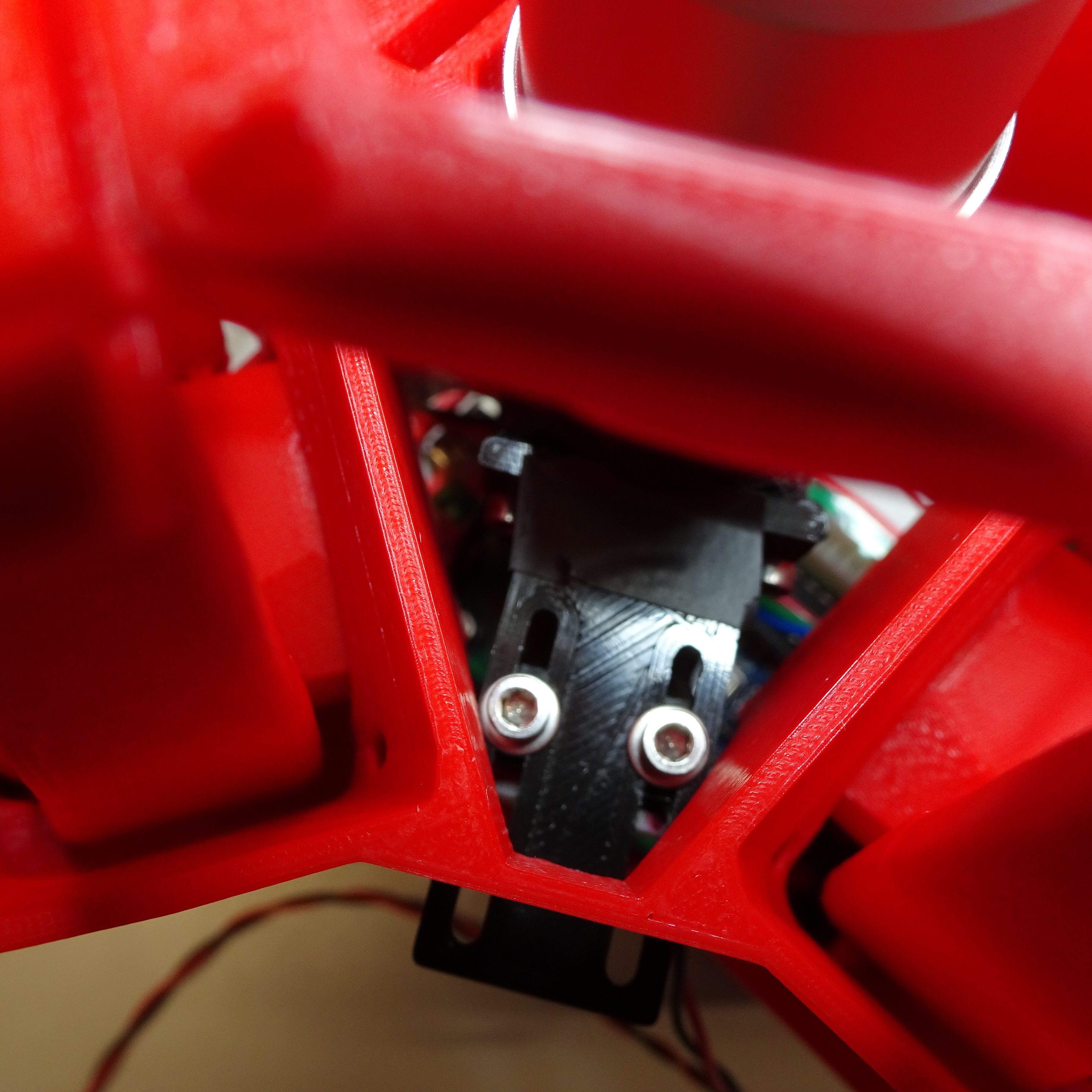
You can move the position of the condenser by loosening these screws.
