Transmission illumination
These instructions show you how to add transmission illumination and optics module to your Delta Stage.
Parts
- 1 LED
- 1 100Ω resistor
- some electrical tape
- 2 female crimp terminal contact
- 1 female connector housing
- 1 condenser lens
- Some solder
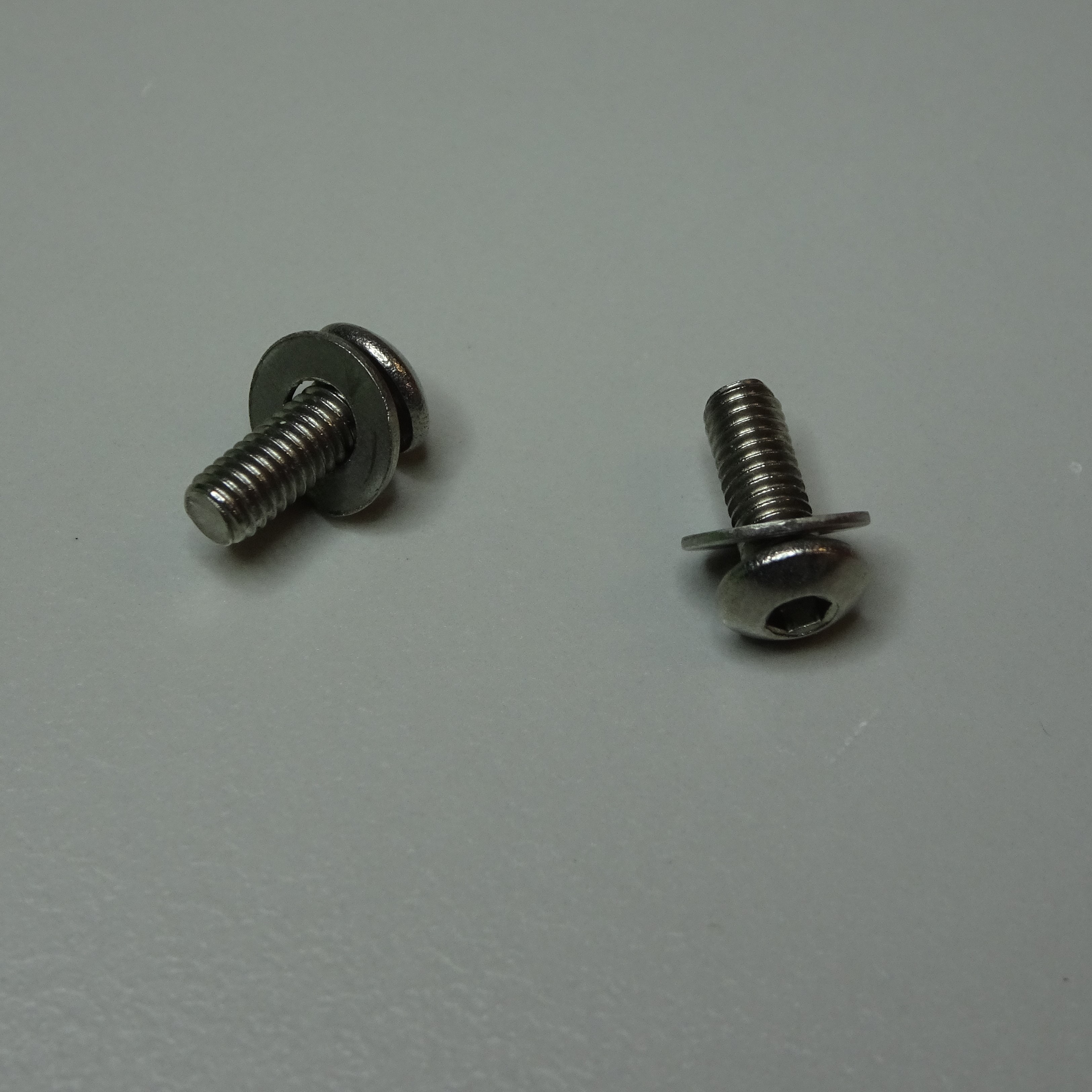
- 2 M3x8mm screw
- 3 M3 nut
- 1 Raspberry Pi camera v2
- 1 objective lens
- 1 tube lens
- 40 cm of red 0.5A instrument wire
- 40 cm of black 0.5A instrument wire
- 6 cm of 3.2mm heat shrink
- 4 cm of 4.8mm heat shrink
- 2 M3 washer
- 2 M2x6mm screws
Tools
- 1 crimp
- 1 wire stripper
- 1 soldering iron
- 1 wire cutters
- 1 heat gun
Printed tools
3D printed parts
- 1 illumination dovetail
- 1 condenser housing Print in black.
- 1 camera cover
- 1 transmission optics module casing Print in black.
Illumination
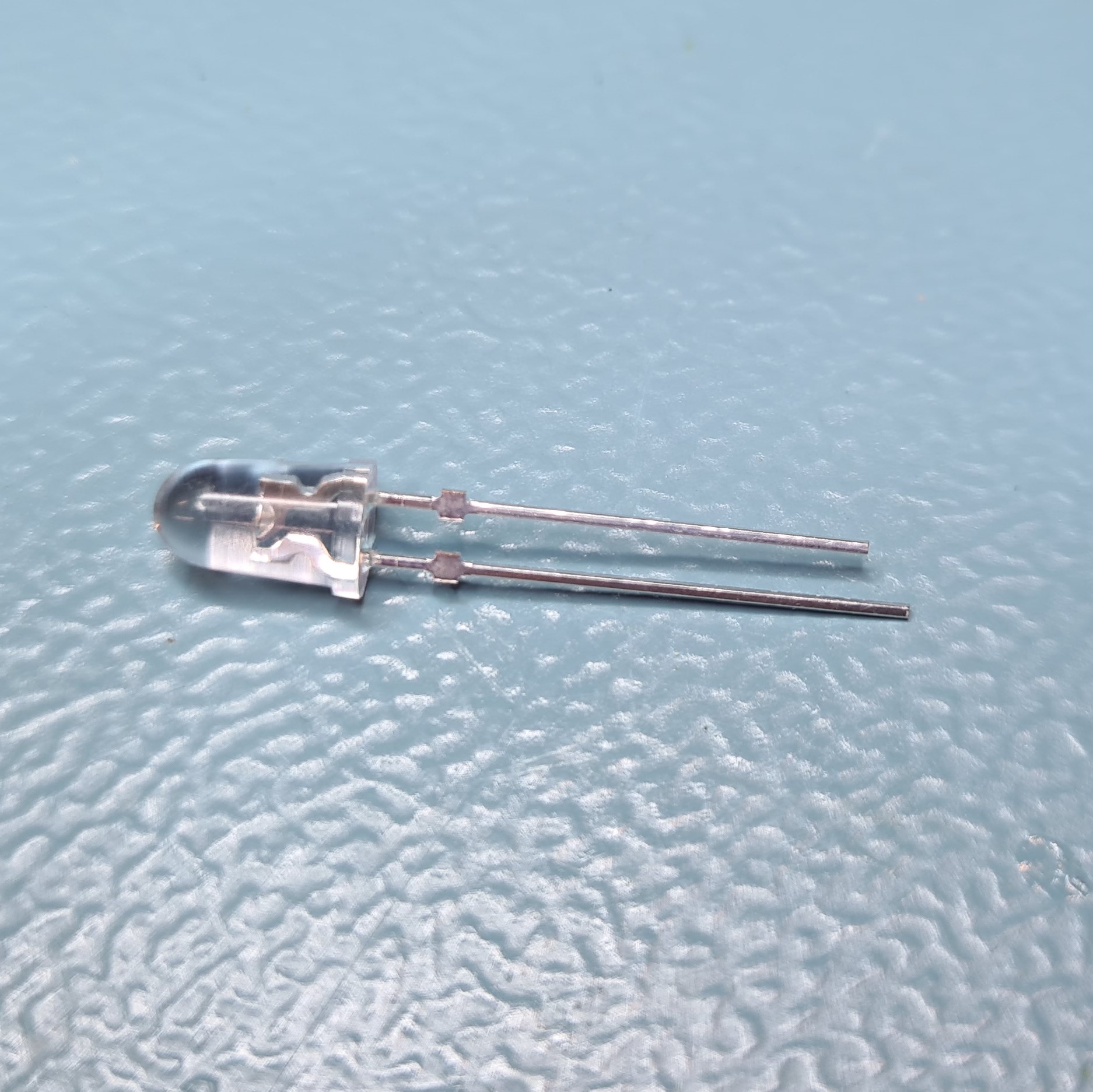
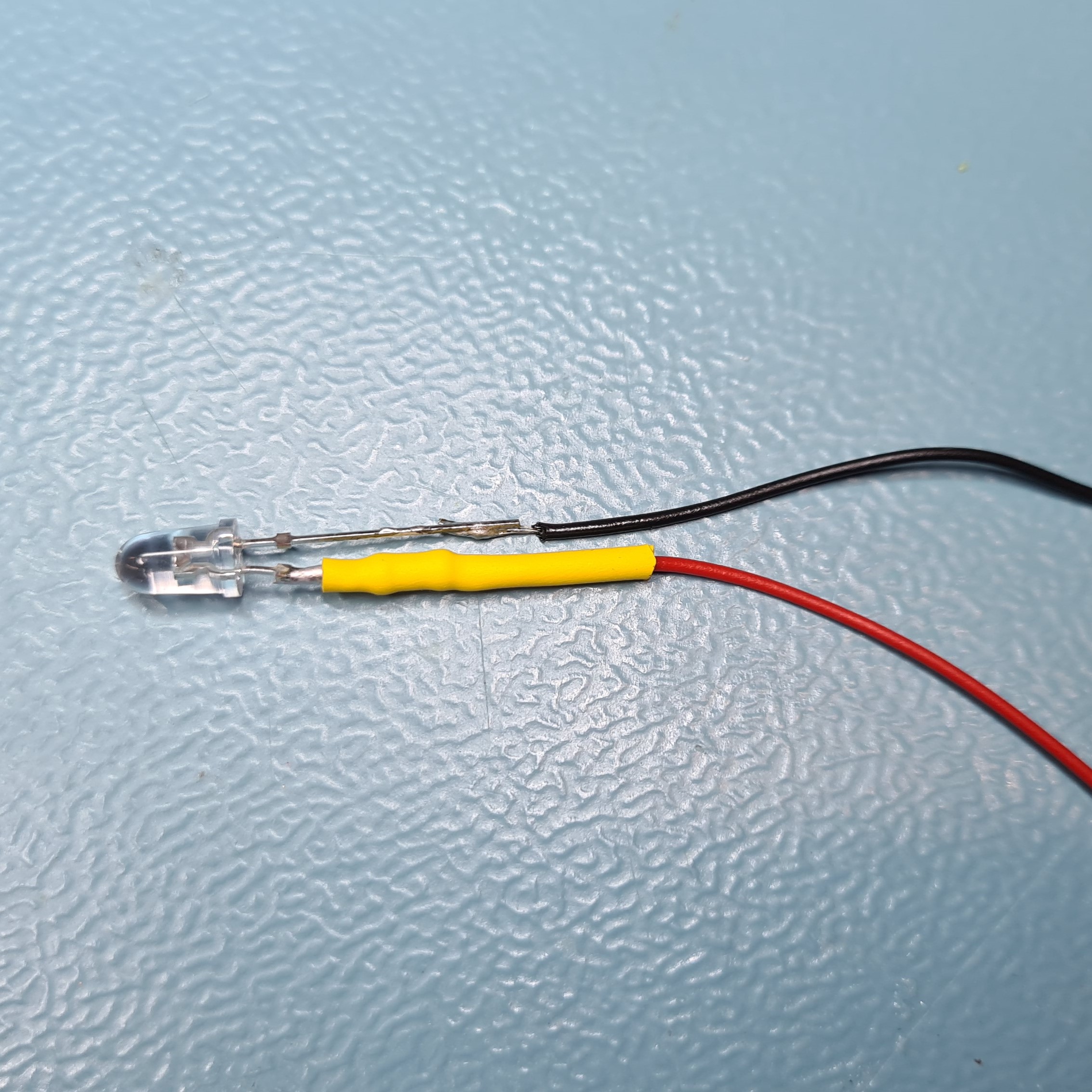
Wire the LED
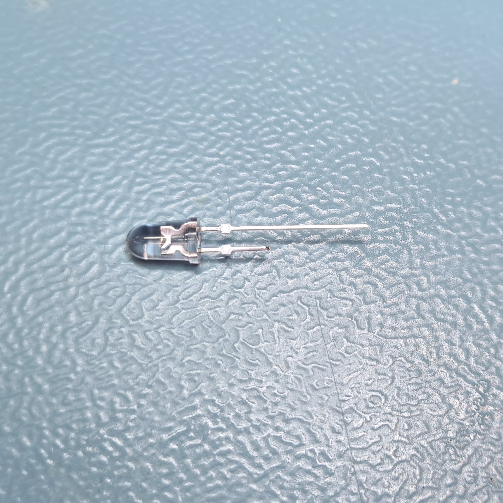
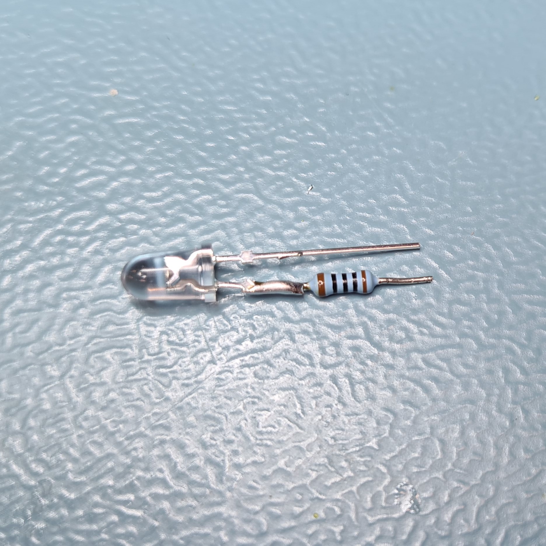
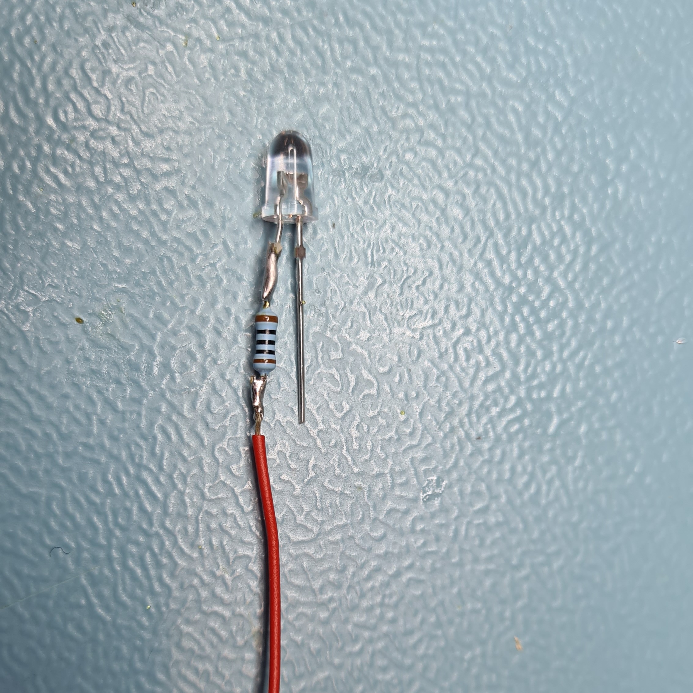
Snip the longer (positive) leg of the LED using wire cutters.
Snip one leg of the 100Ω resistor using wire cutters.
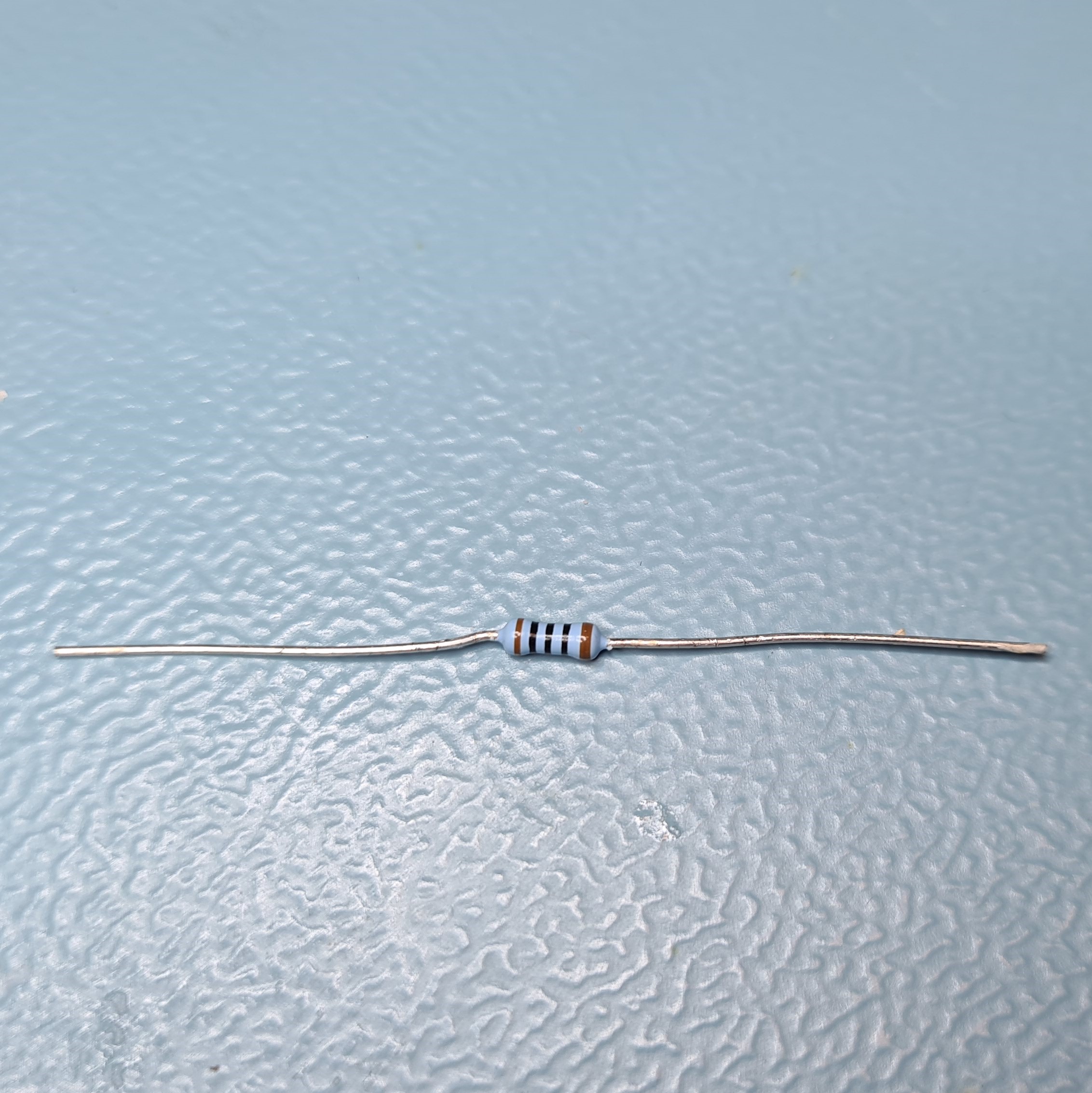
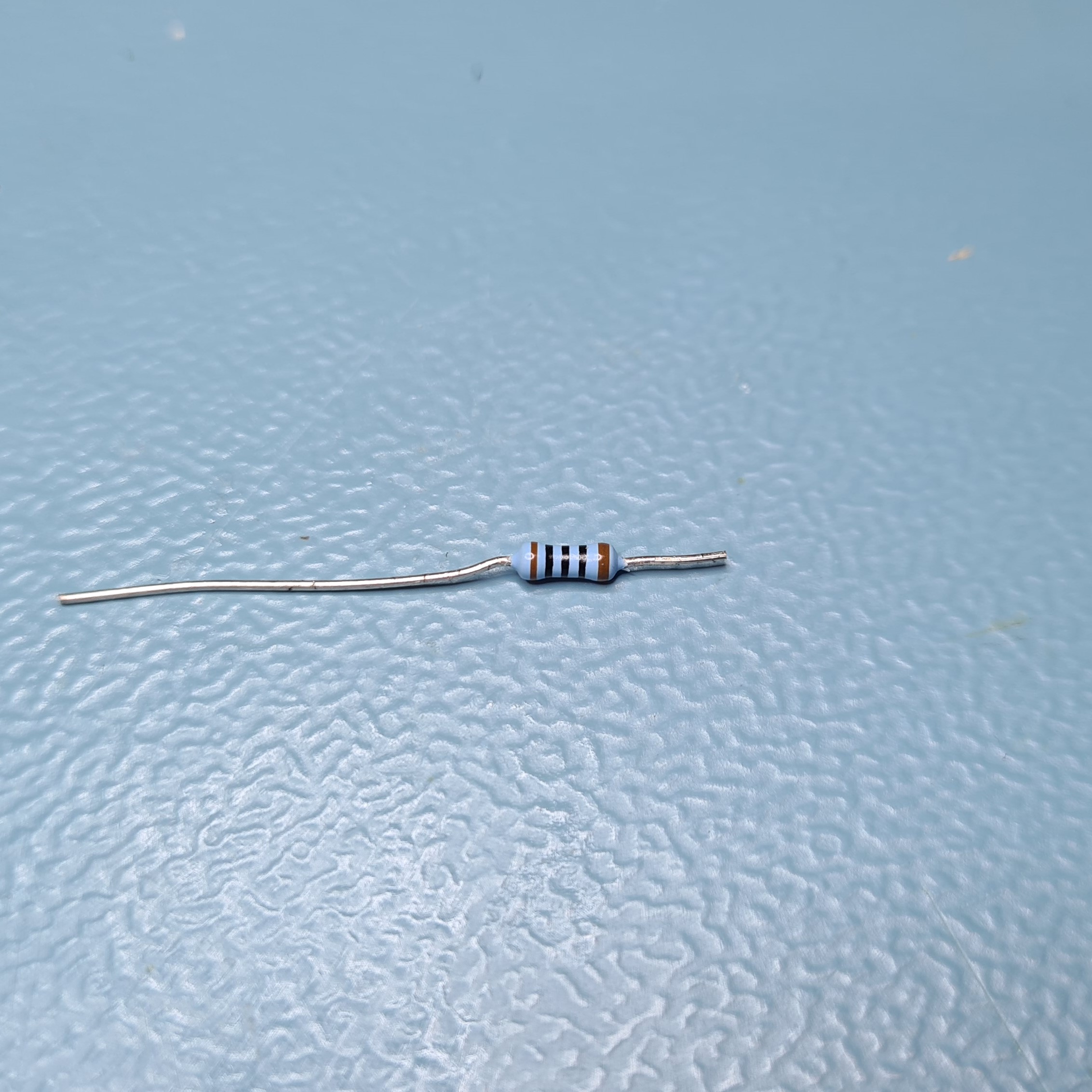
Solder the shorter leg of 100Ω resistor to the positive leg of the LED with a soldering iron and solder. Snip the leg of the resistor so that the two legs are approximately the same length using wire cutters.
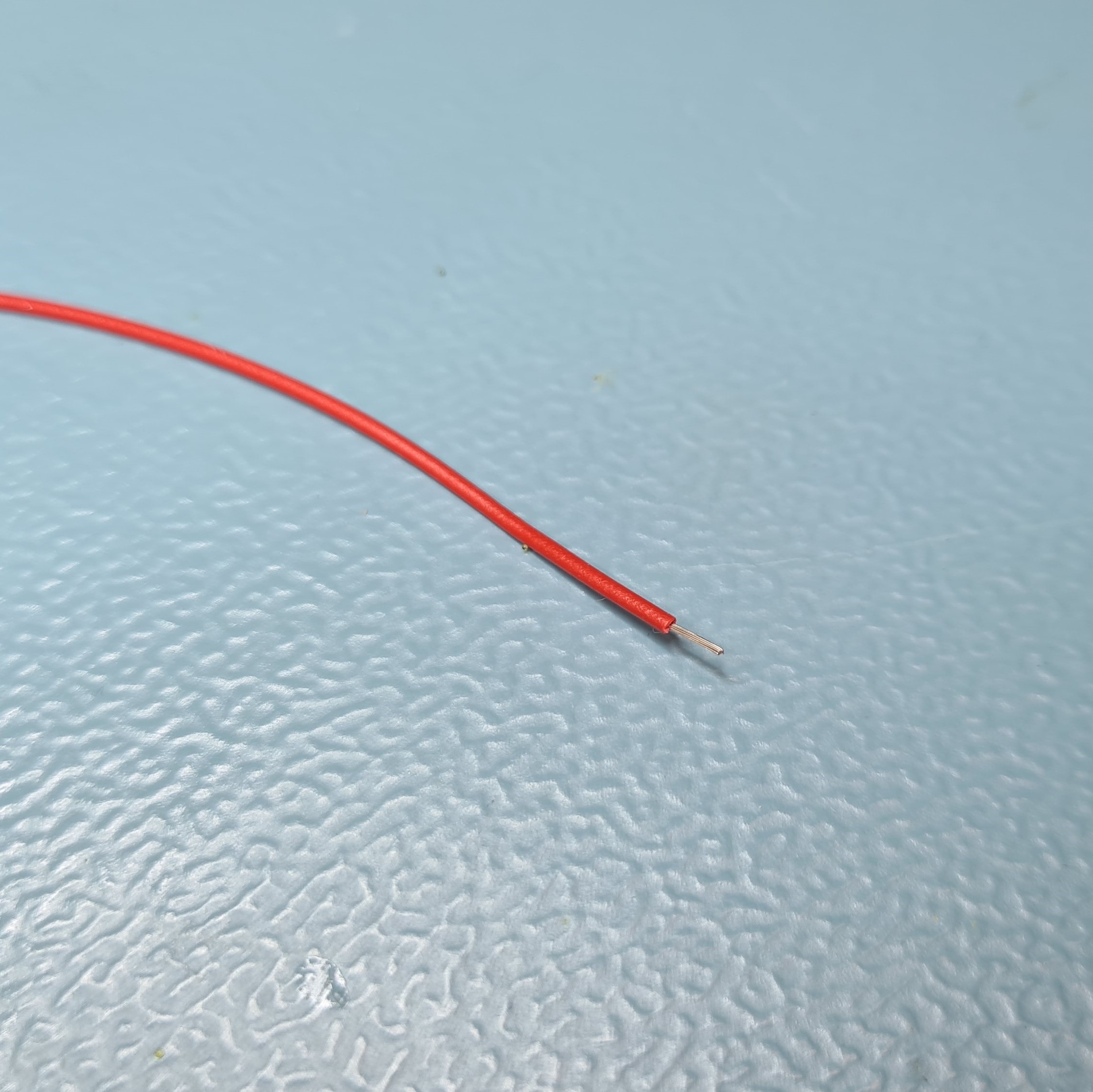
Cut the red 0.5A instrument wire and the black 0.5A instrument wire to 40cm lengths using wire cutters.
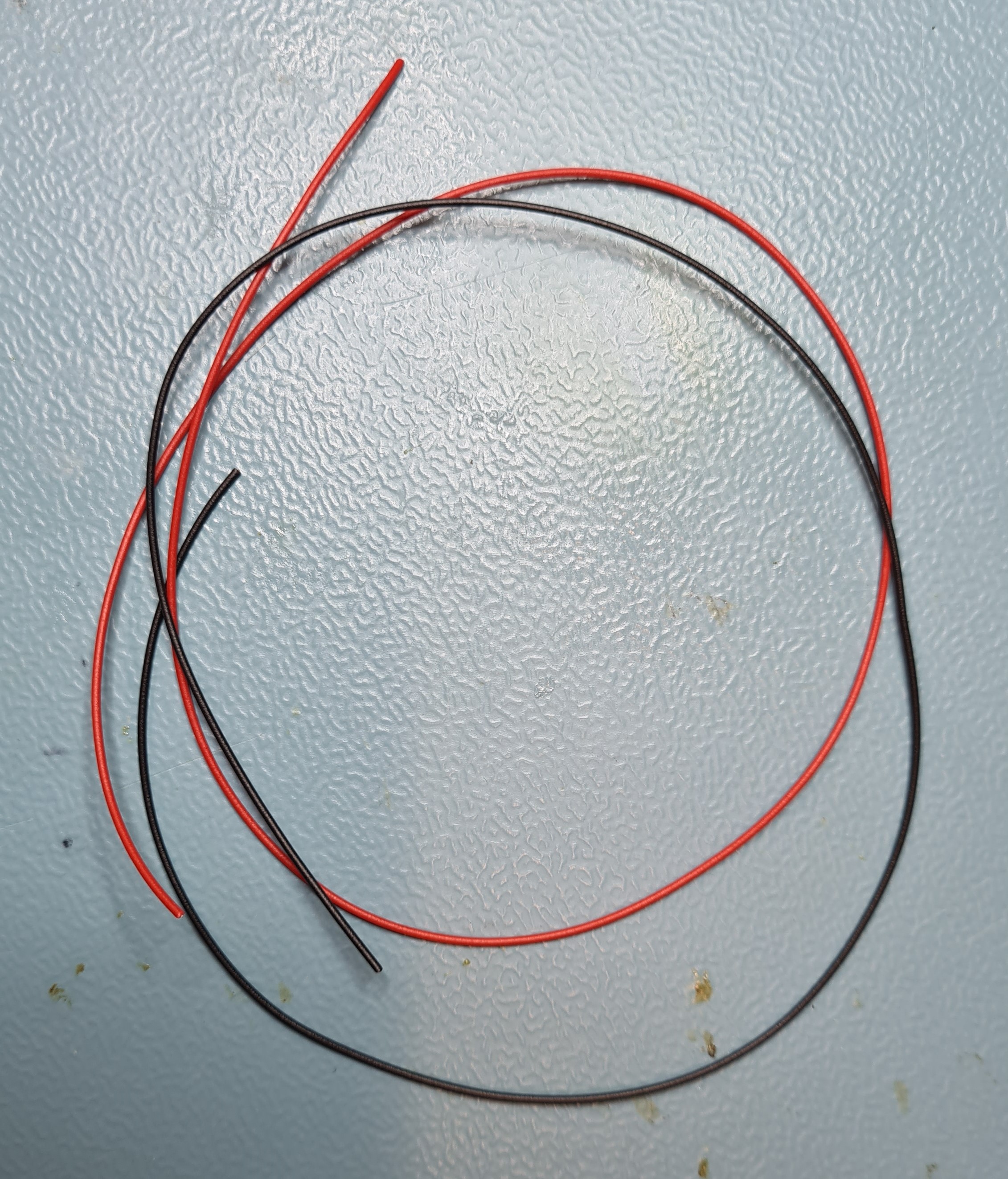
Strip both ends of the red 0.5A instrument wire and [black 0.5A instrument wire ] with a wire stripper.

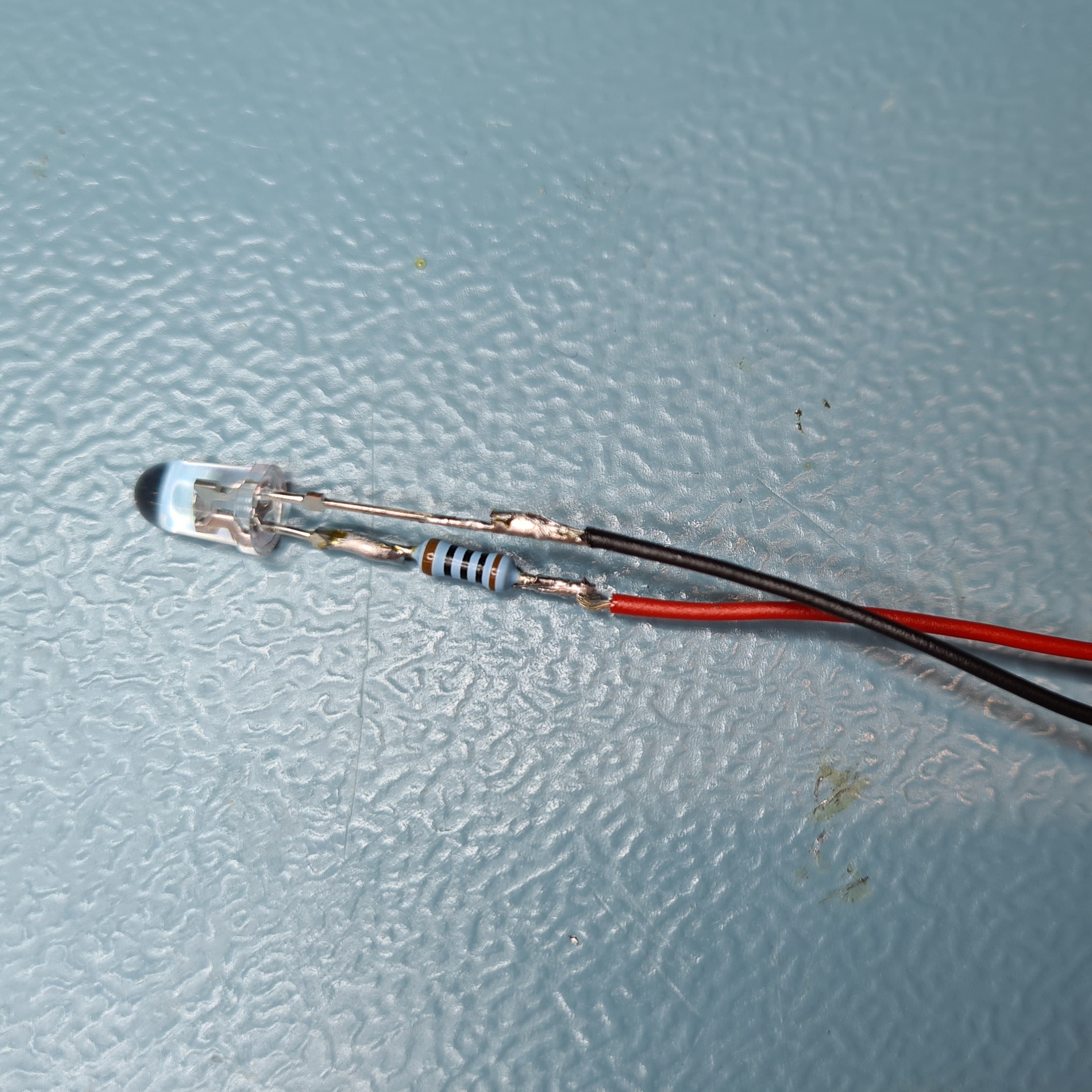
Solder the red 0.5A instrument wire on to the free leg of the [330Ω resistor] using a soldering iron and solder.
Solder the black 0.5A instrument wire on to the free leg of the LED using a soldering iron and solder.
Cover each leg of the LED and resistor with some 3.2mm heat shrink so that the exposed metal cannot short-circuit. Use a heat gun to heat the 3.2mm heat shrink on both legs.
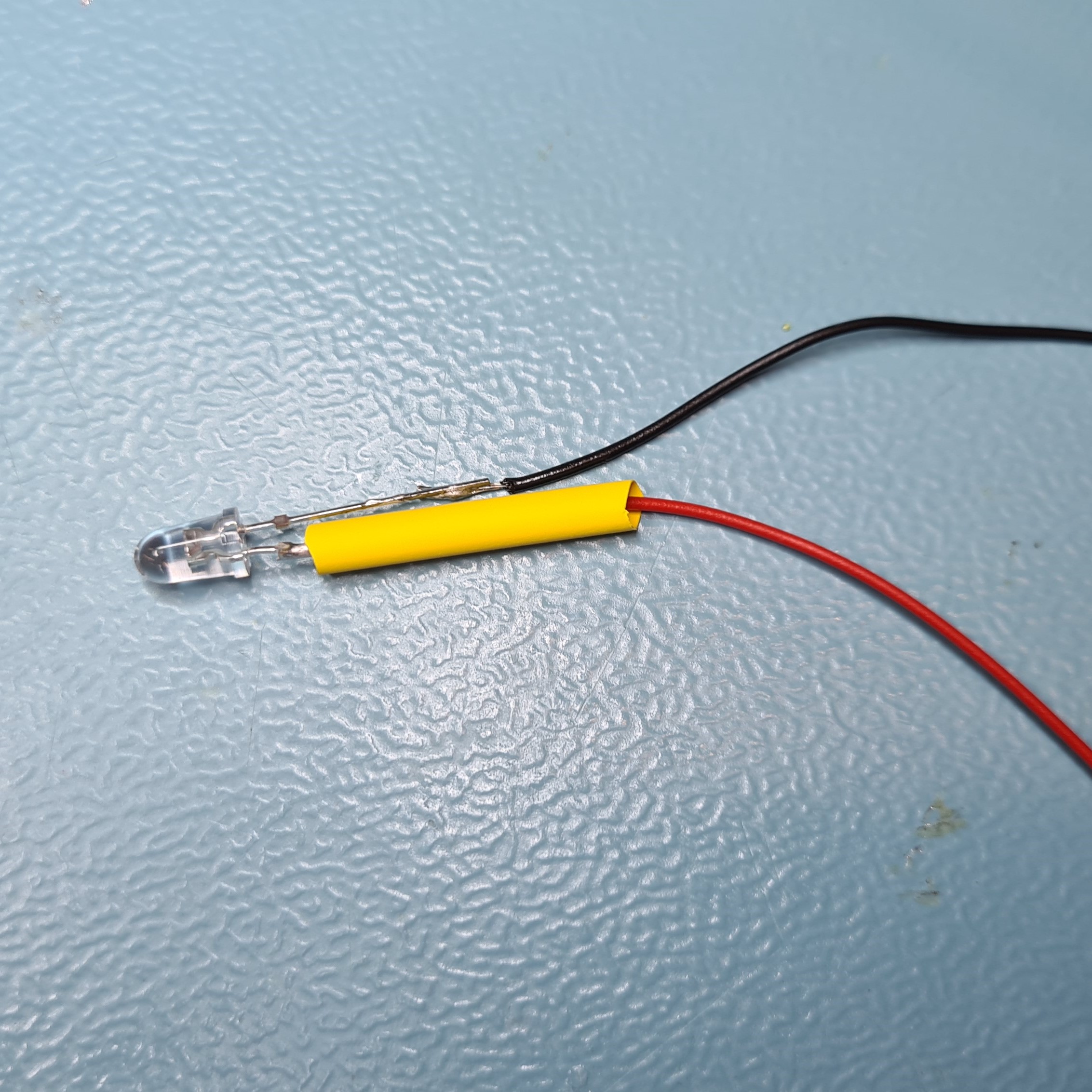
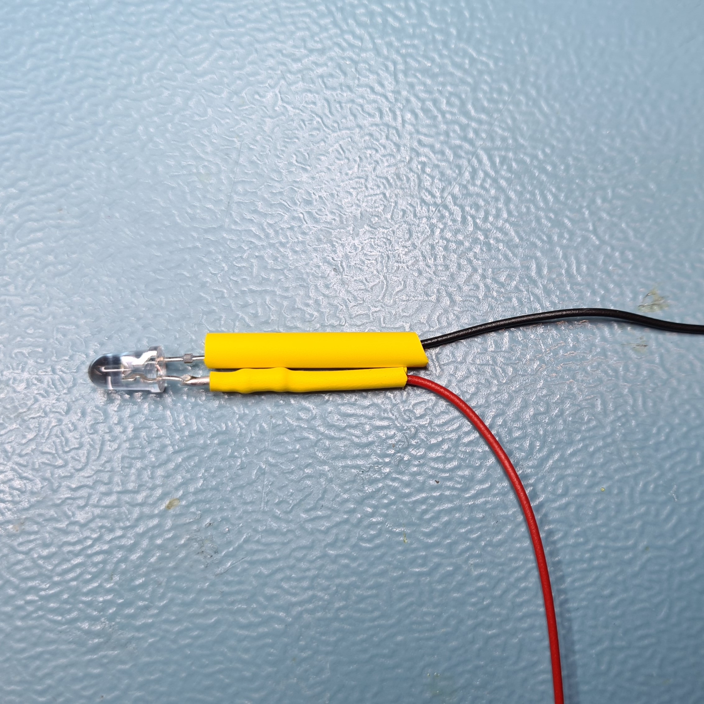
Slide some 4.8mm heat shrink over both heat shrinks and heat with a heat gun.
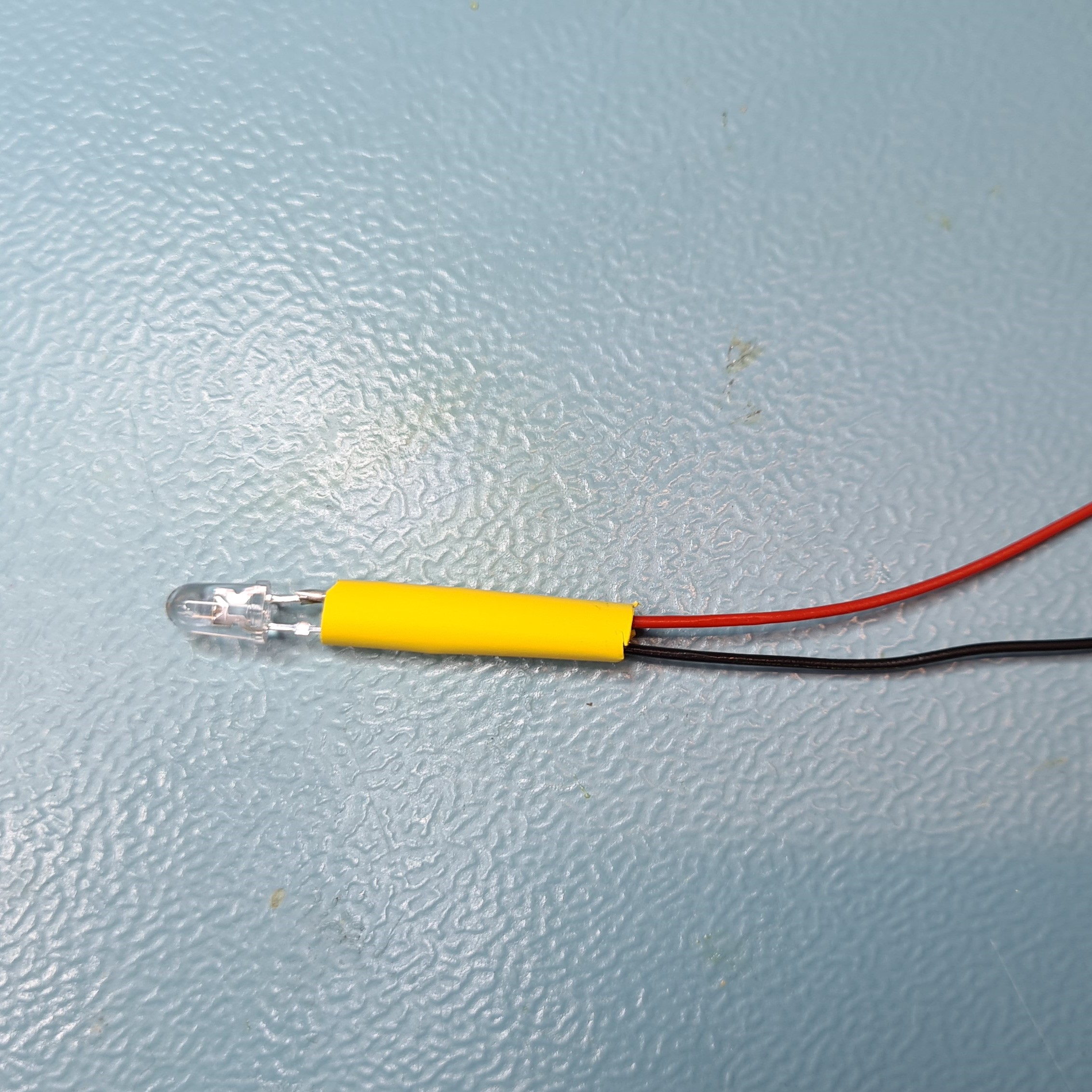
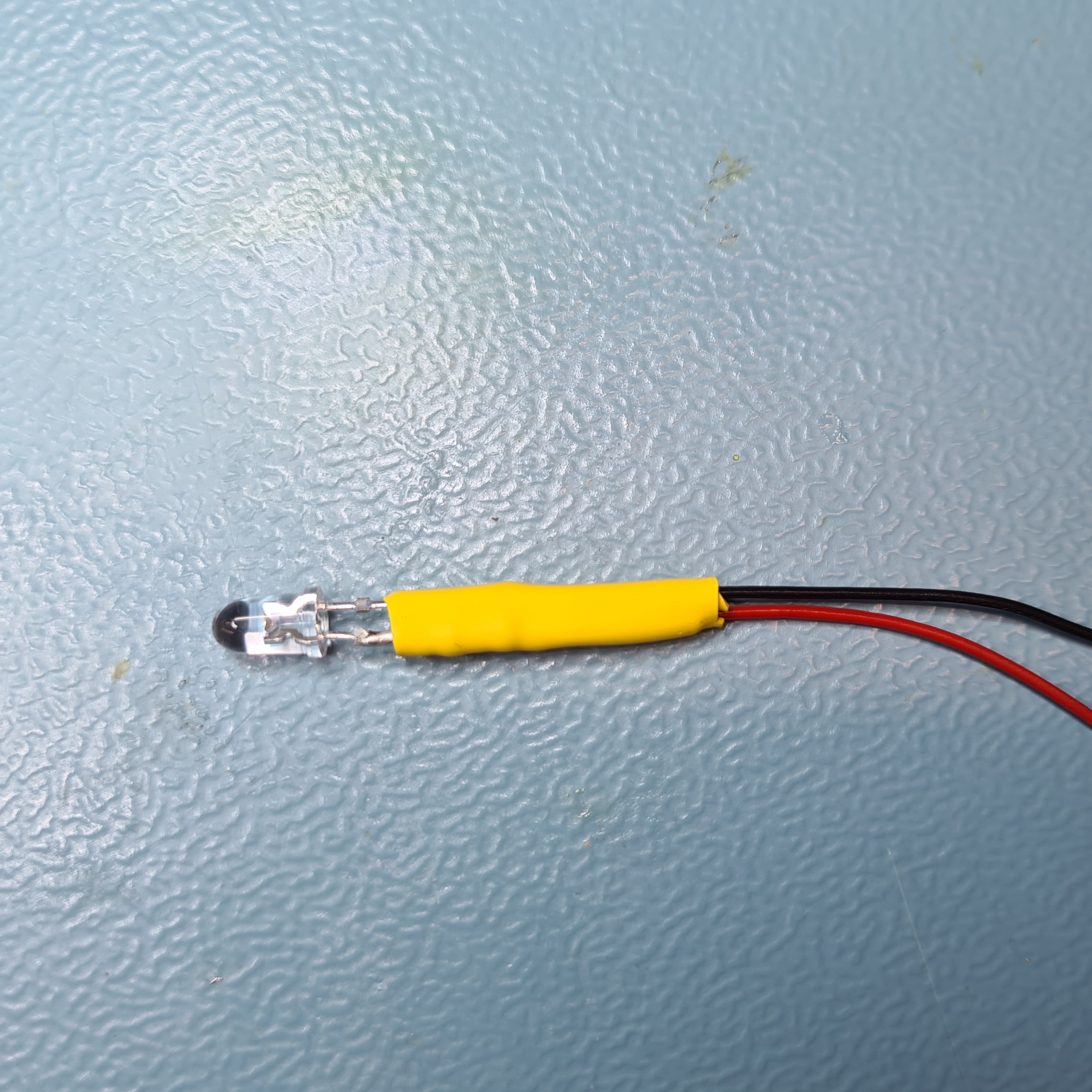
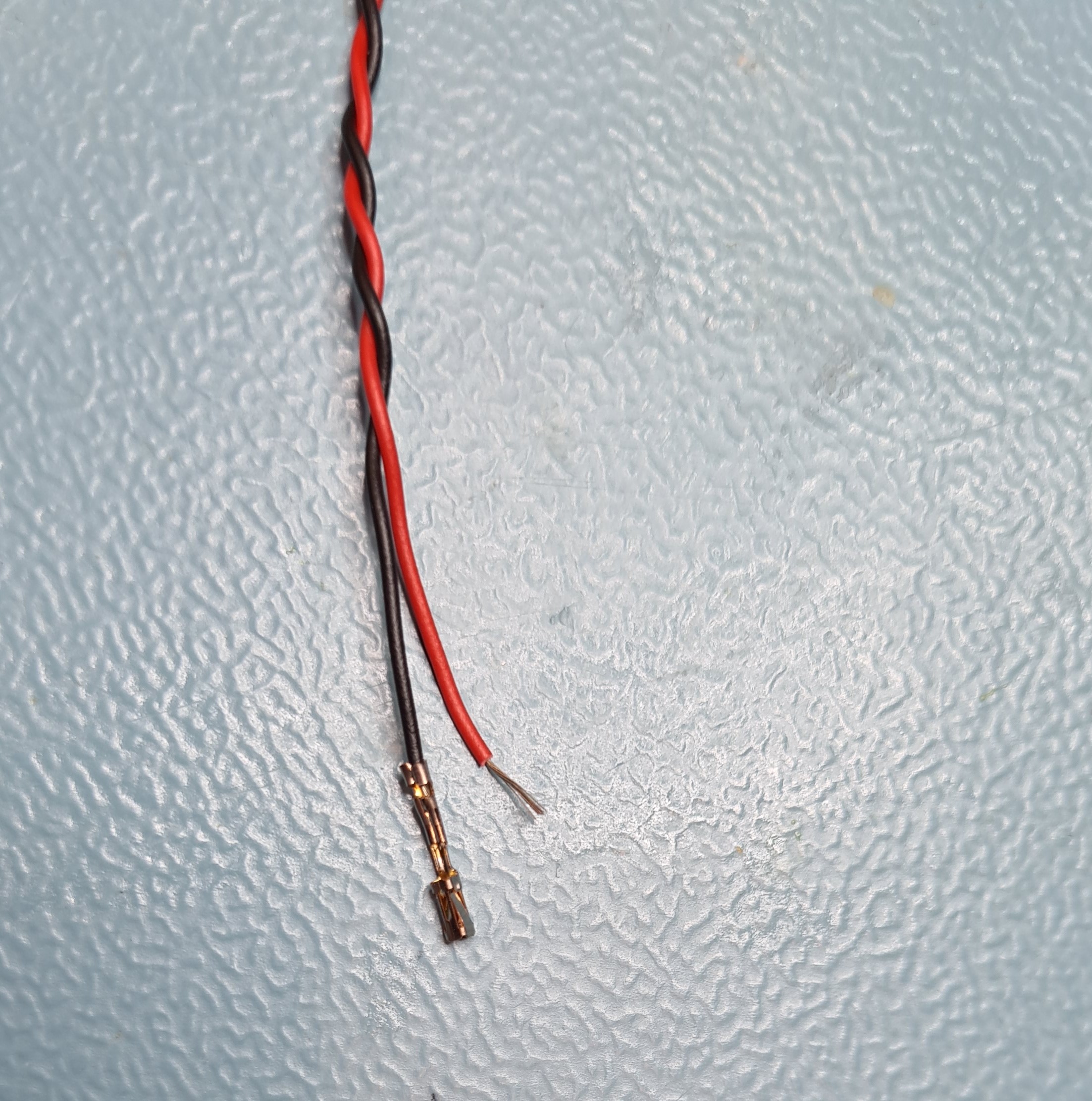
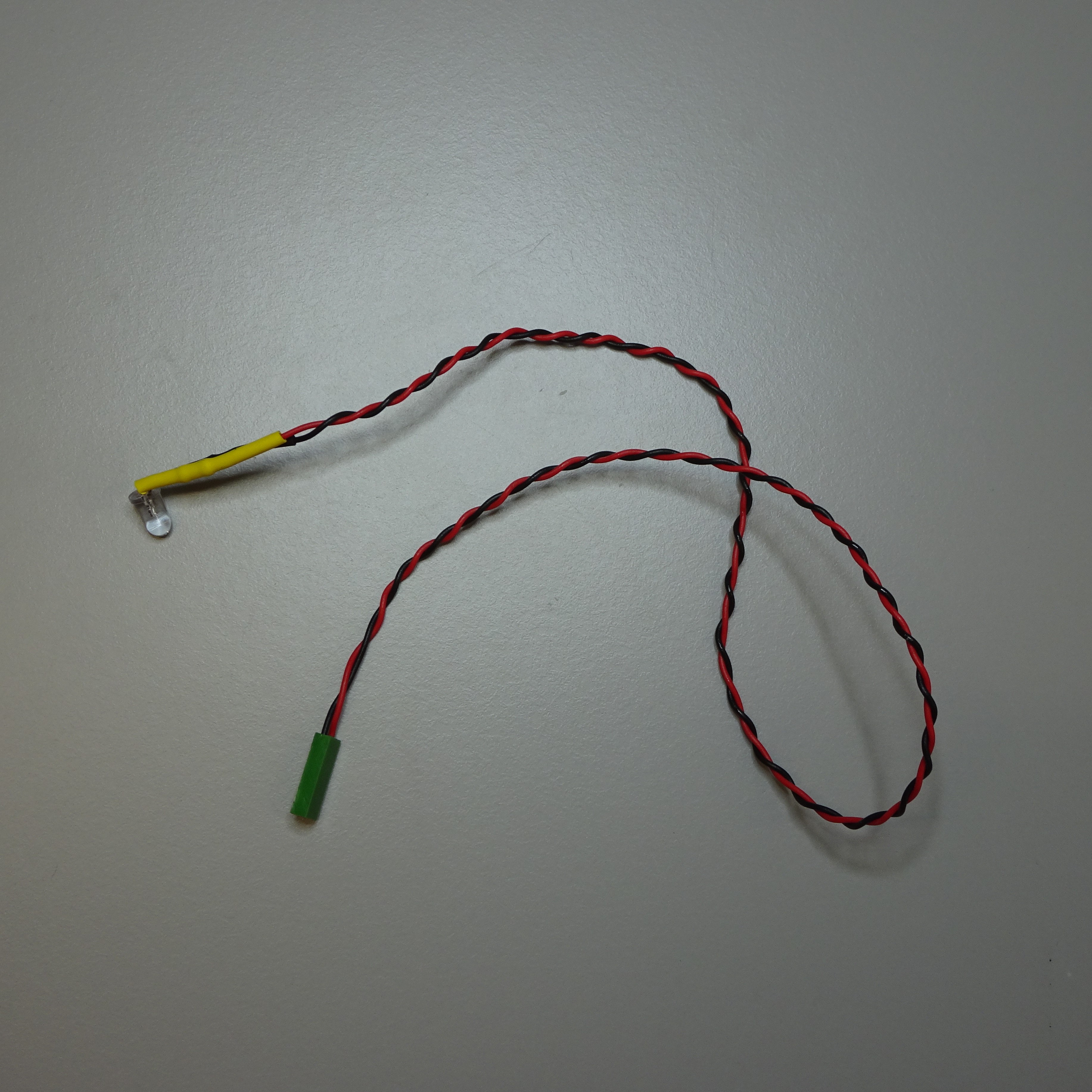
Twist the two wires together. If they are not the same length then trim and re-strip.
Using a crimp, crimp a female crimp terminal contact on to the ends of both the wires.
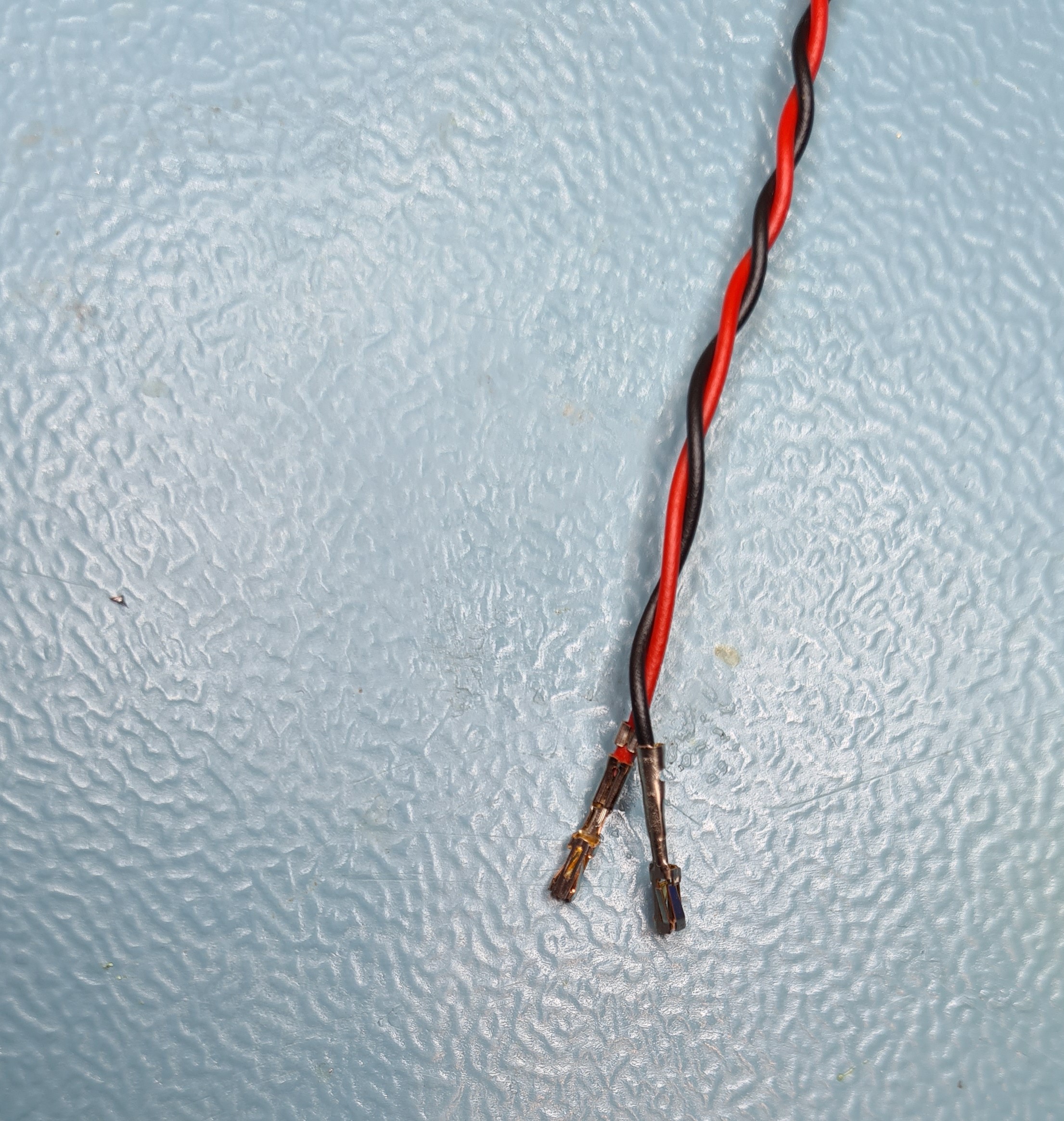
Push both crimp terminals into a female connector housing.
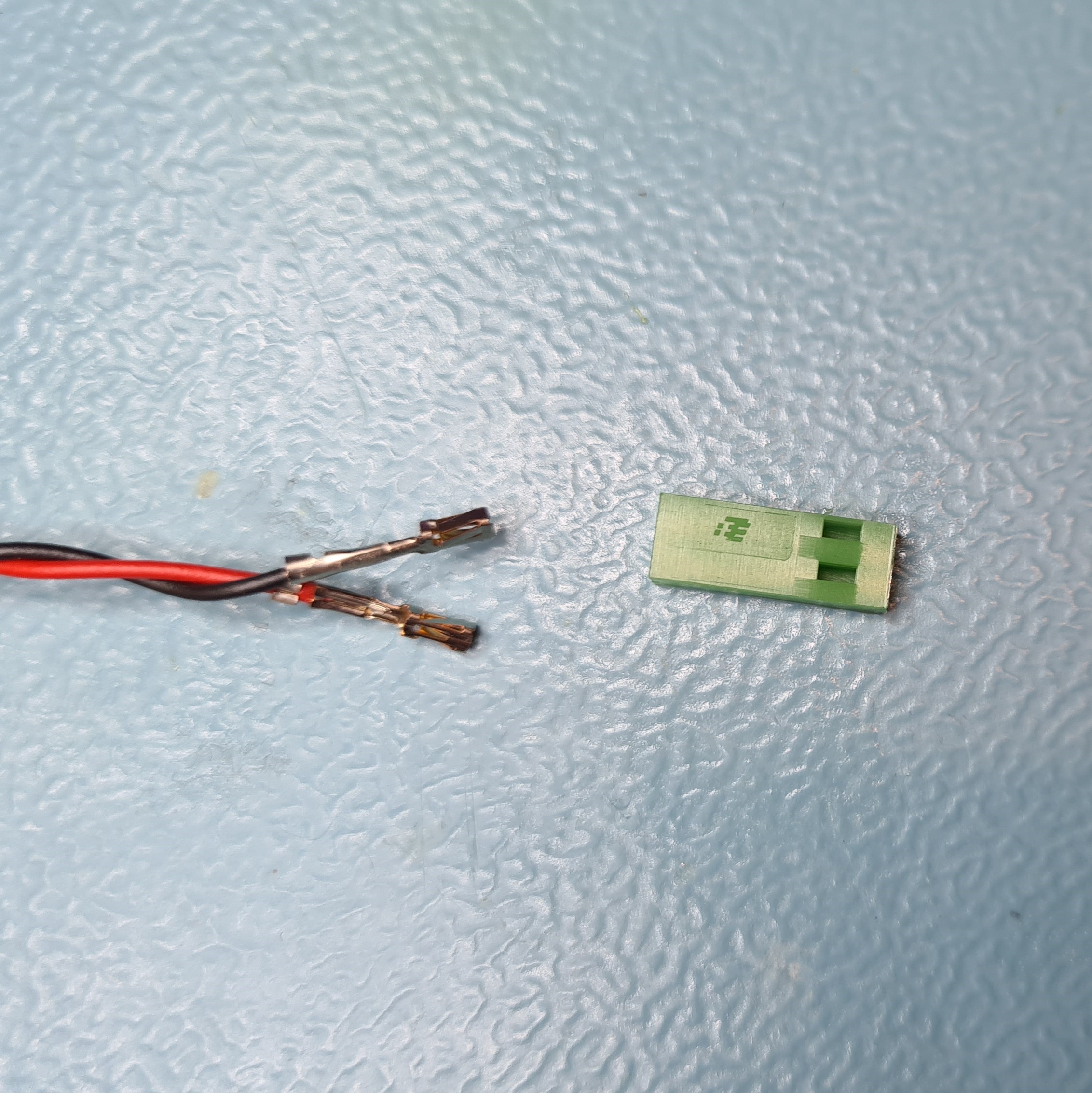
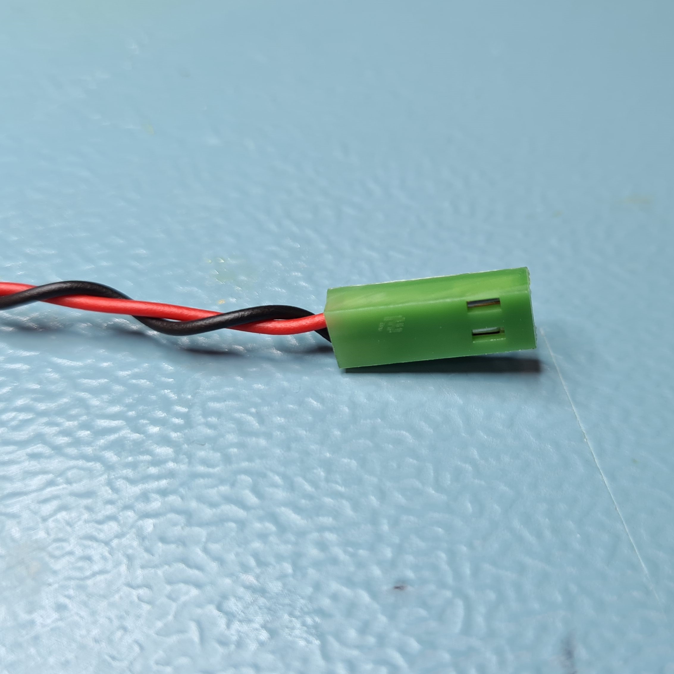
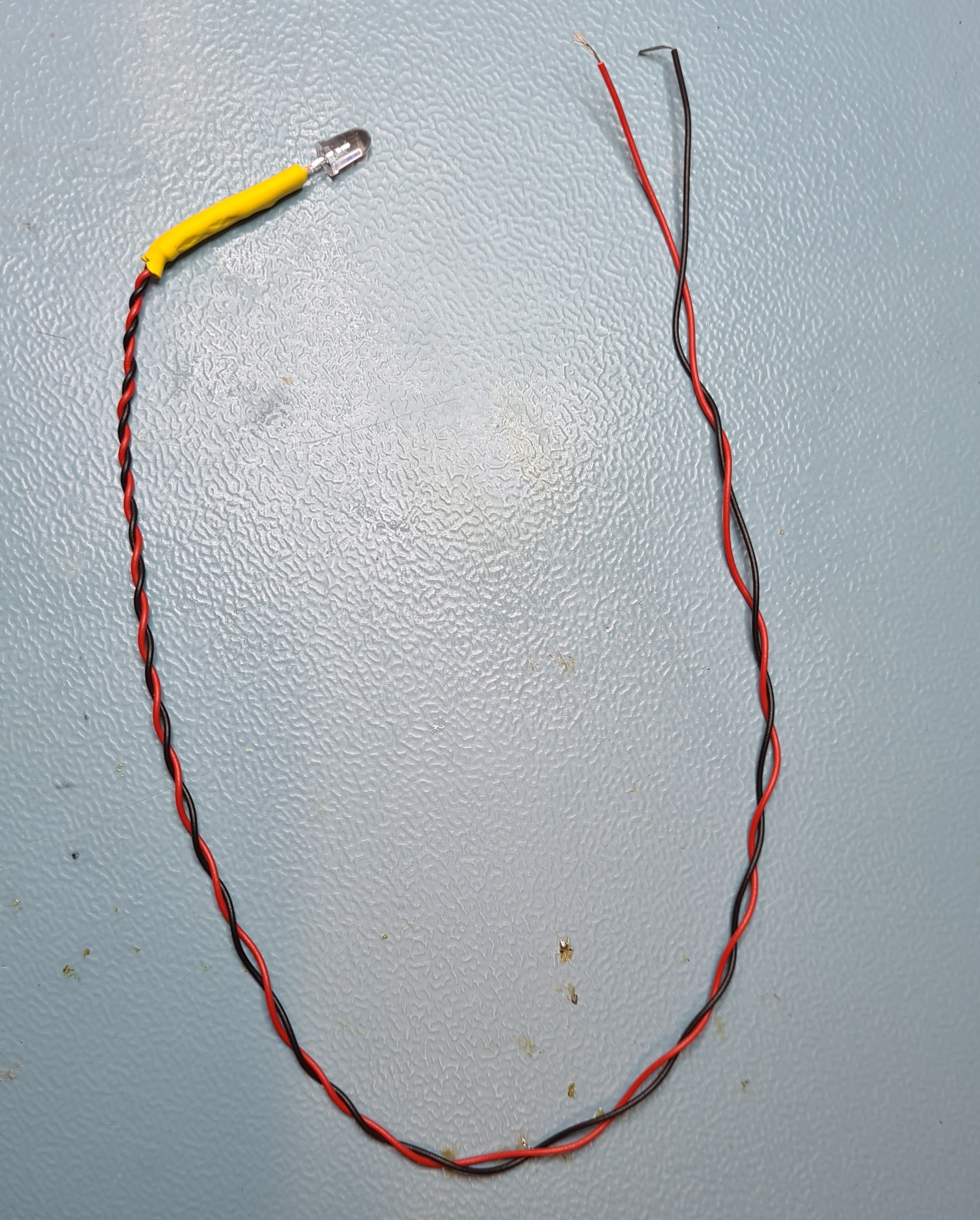
You have now made a wired LED.
Insert the Condenser Lens
Take a condenser lens and place it on top of the lens tool with its flat side down.
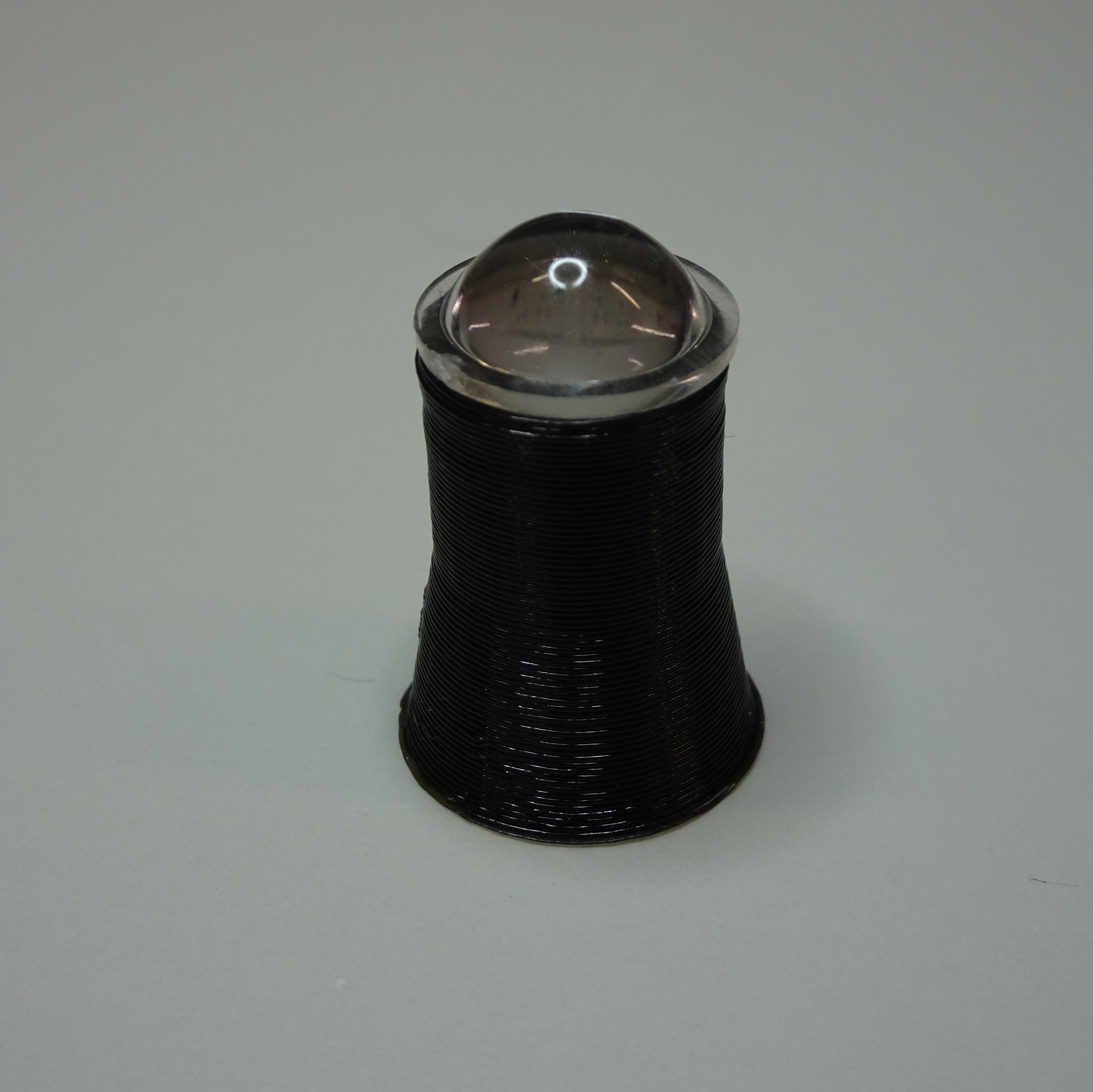
Push the condenser housing down vertically on top of the lens. make sure it is flat, pushing again harder if necessary.
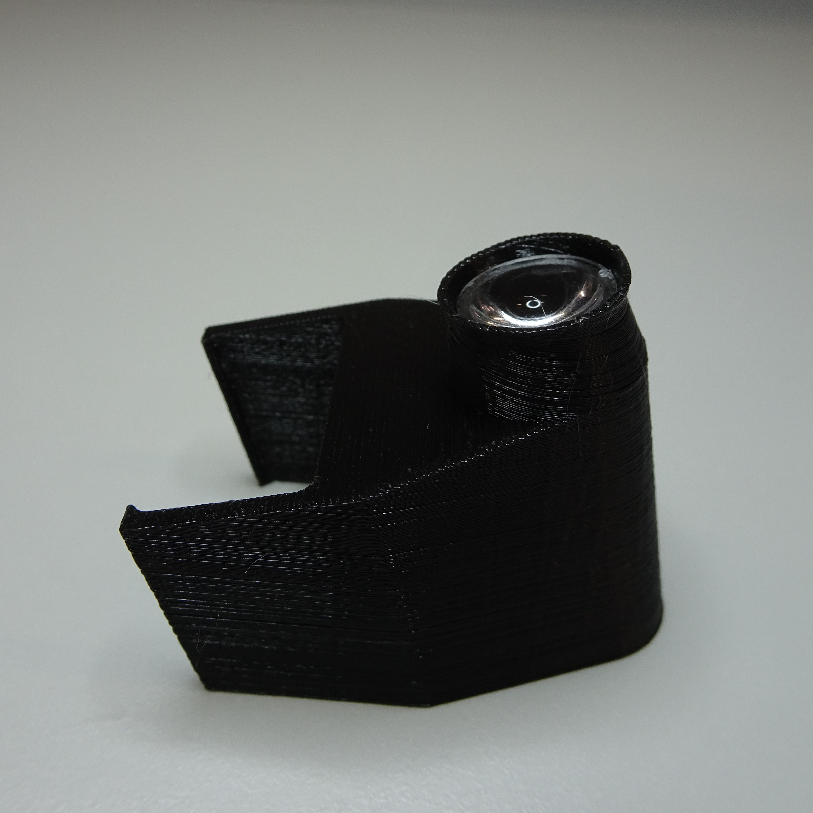
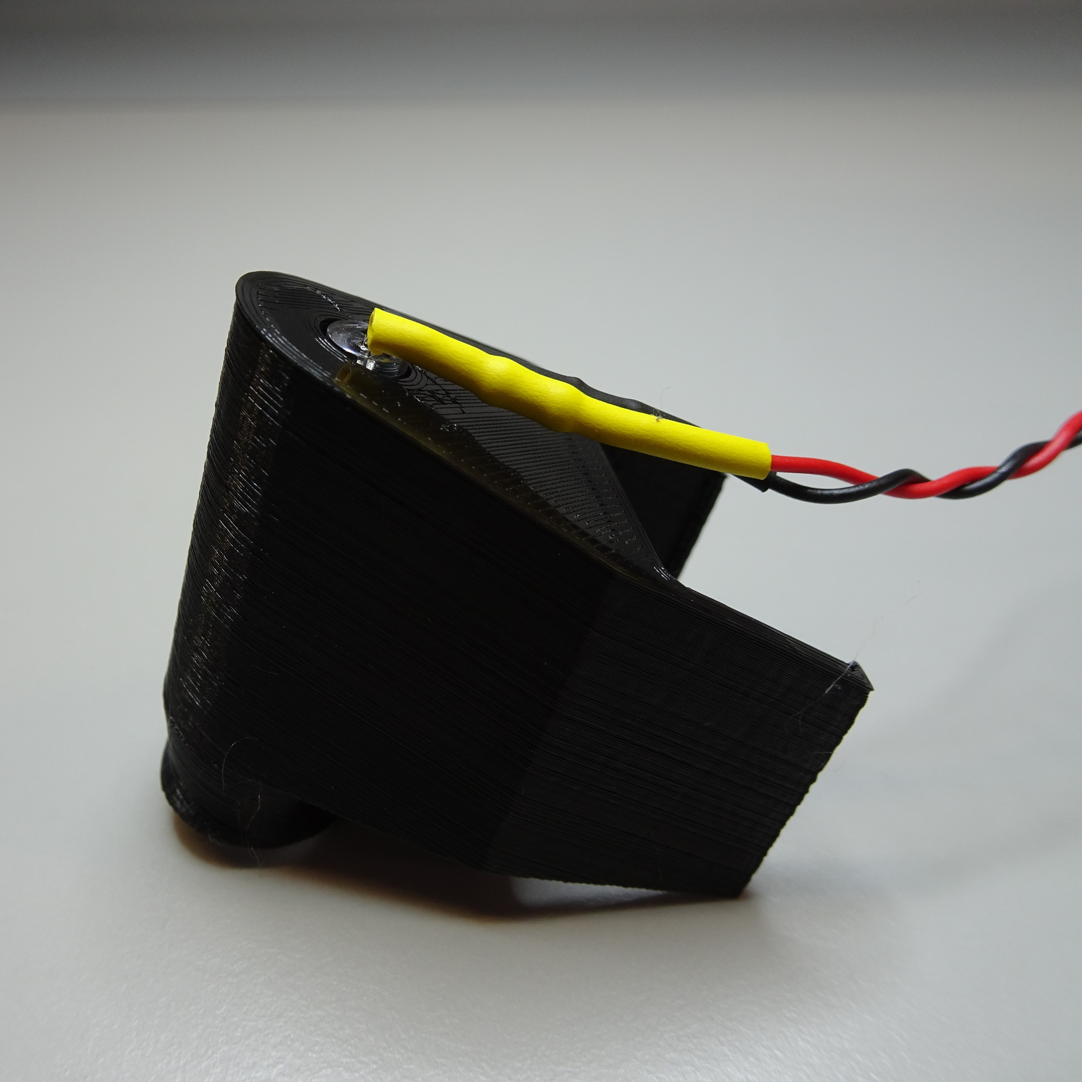
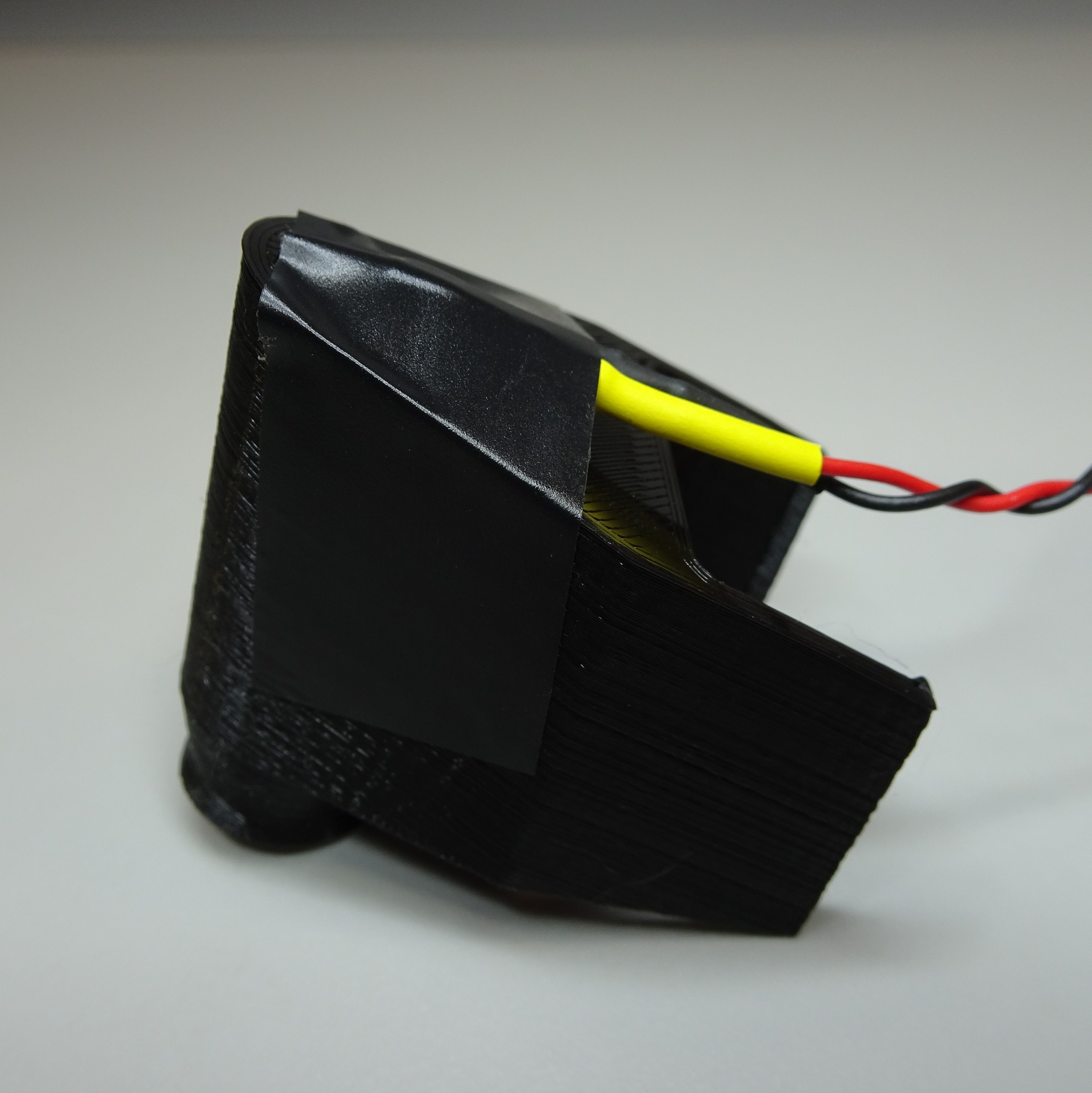
Insert the LED
Push the LED into the top of the condenser housing. If it is loose, secure it in place with some electrical tape.
Attach the illumination dovetail
Put the illumination dovetail on the condenser mount of the main body.
Put one M3 washer on to two M3x8mm screws.
Insert two M3 nuts into the nut slots on the condenser mount.
Screw the illumination dovetail onto the main body.
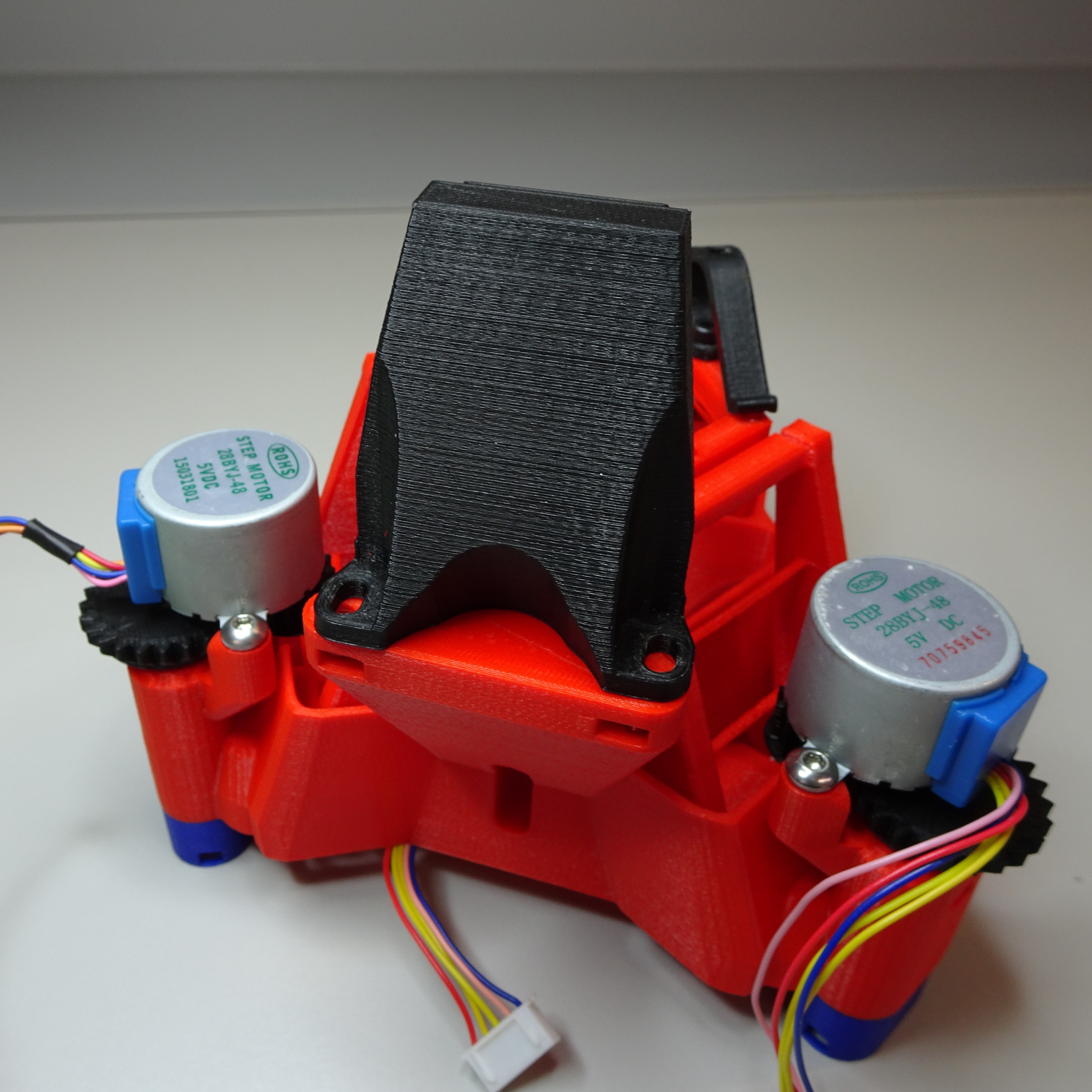
Attach the condenser on to the dovetail
Slide the condenser housing down the dovetail. You can adjust its position up and down by sliding it on the dovetail. You can move it back and forward by loosening the dovetail and and tightening it when it is the correct position.
Optics Module
Clean the optics module casing
After printing the transmission optics module casing there may be strings or dust. Clean these out so they won't block the light or fall onto the camera sensor.
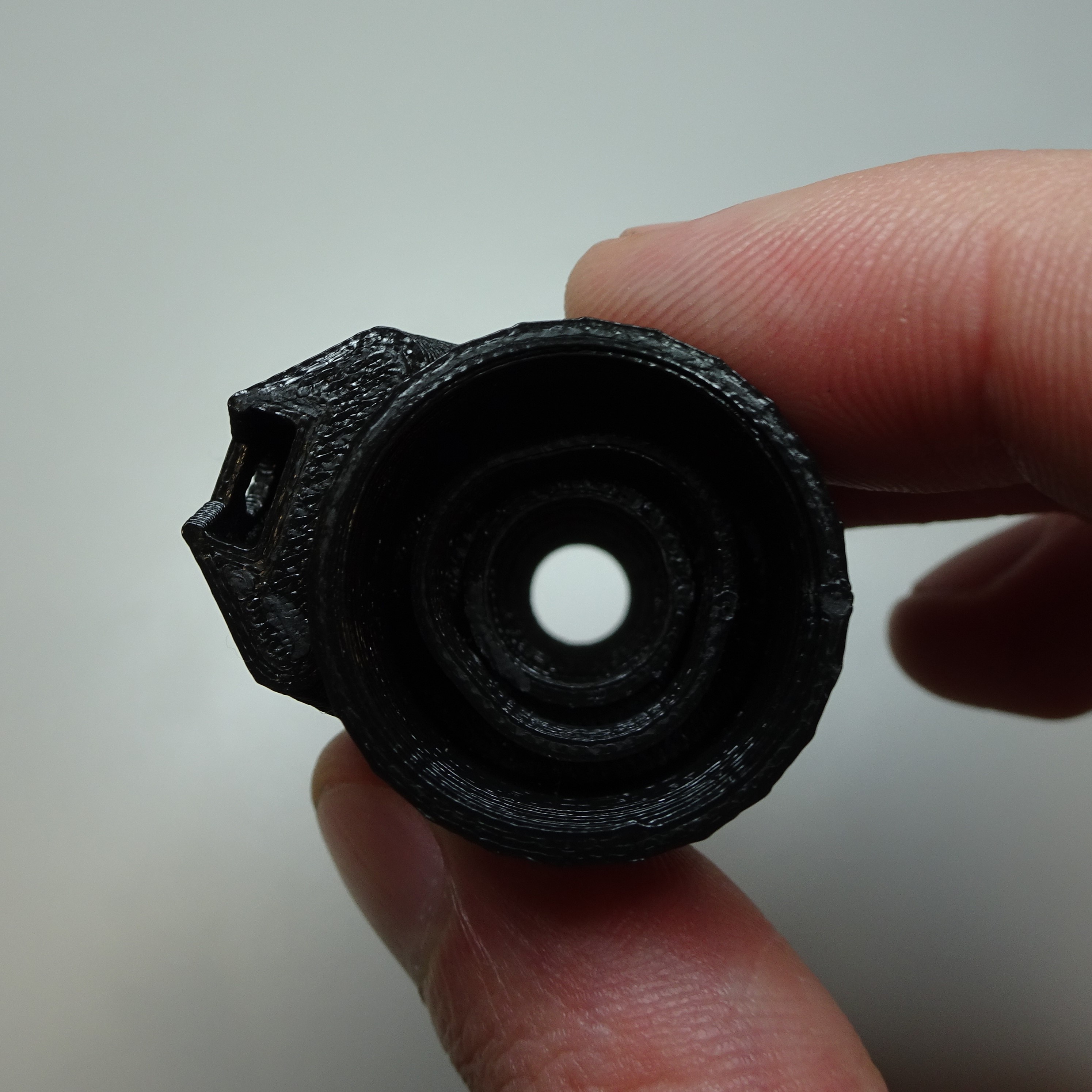
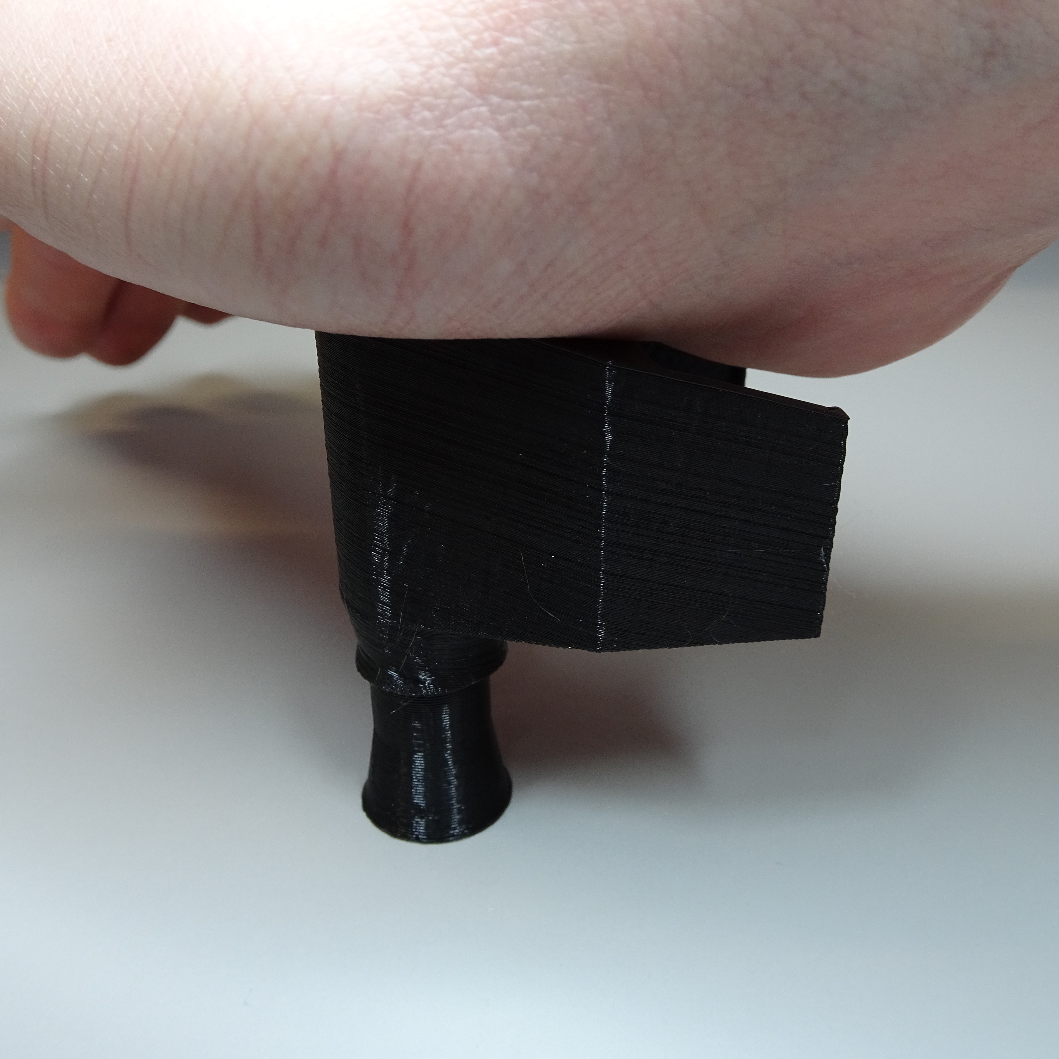
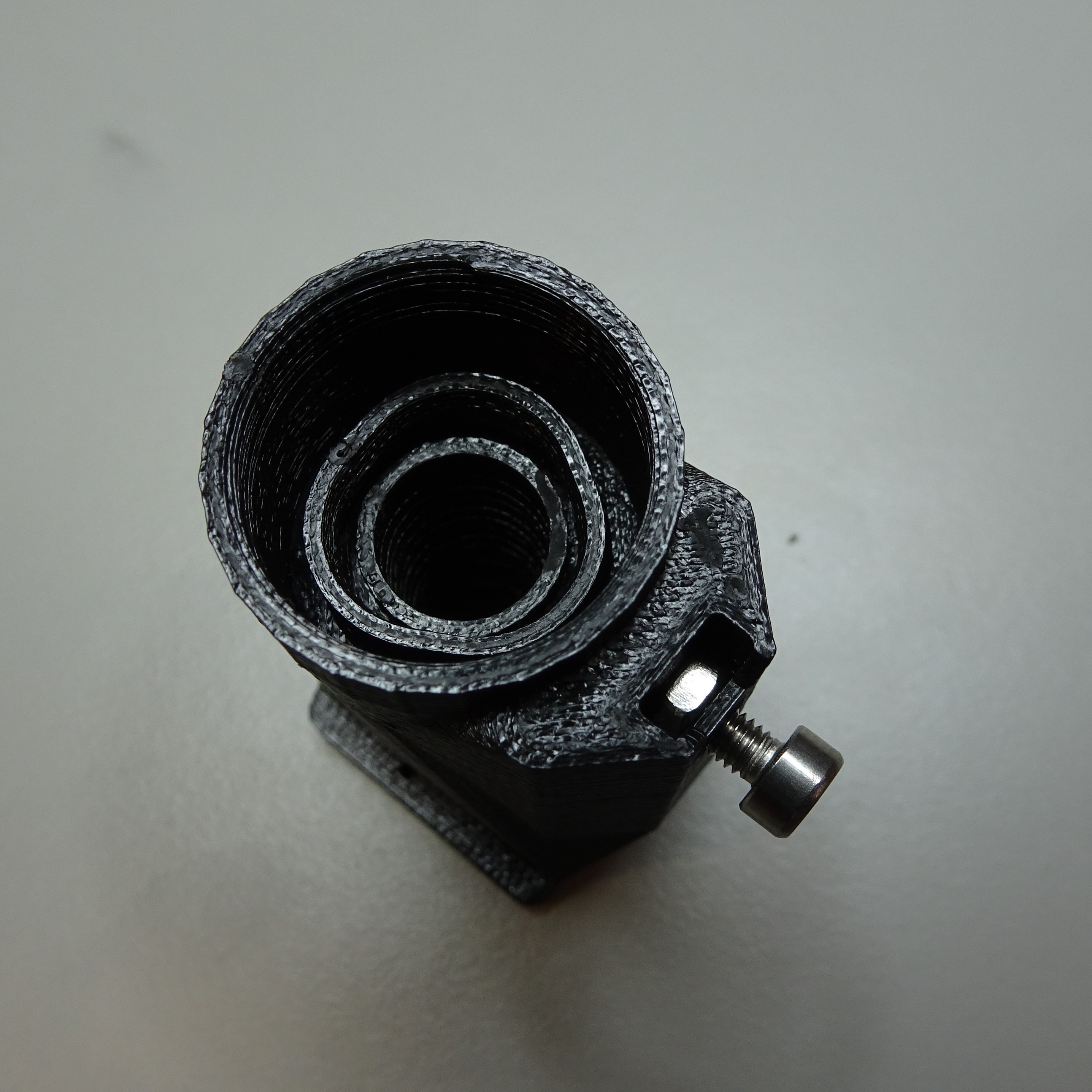
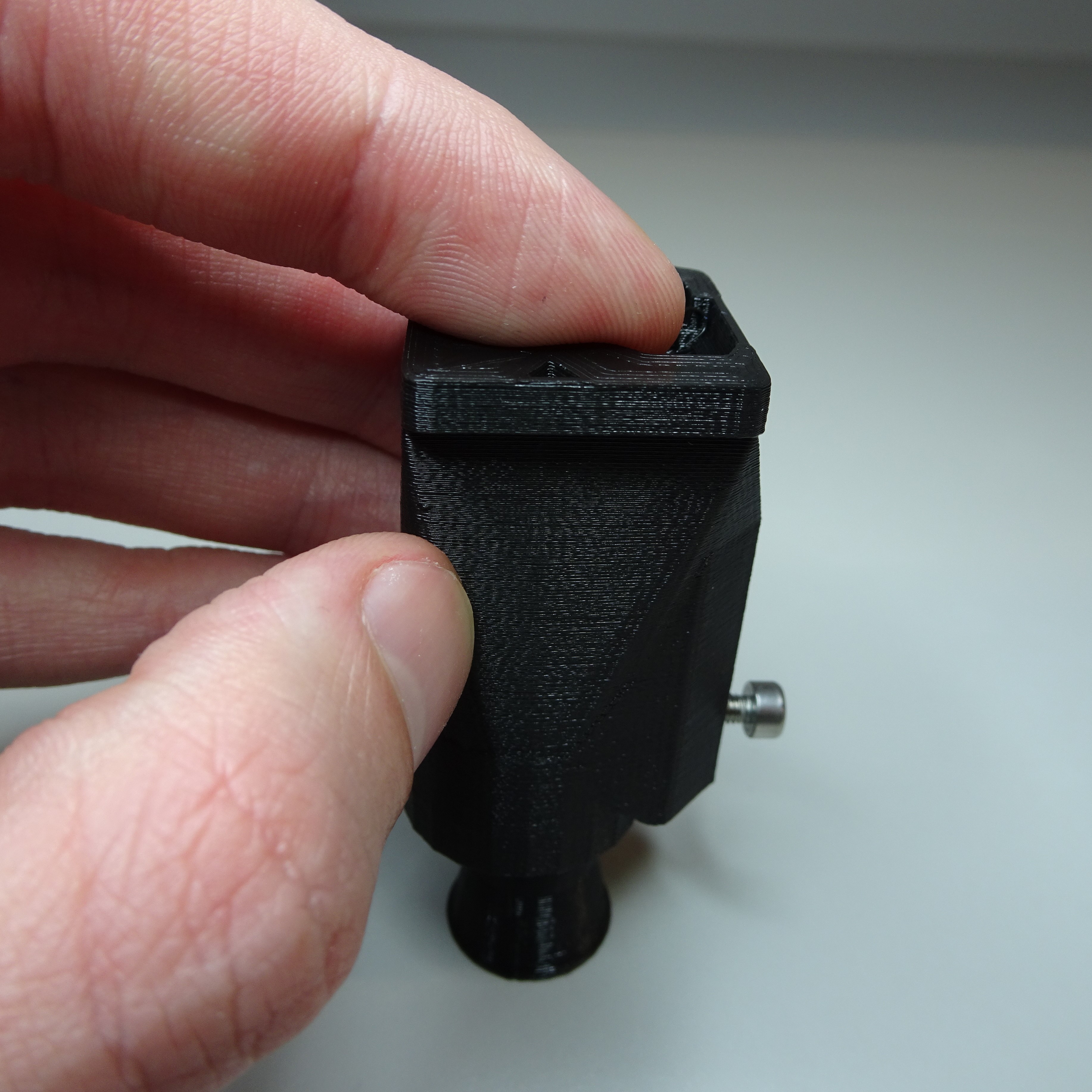
Attach the objective screw
Slide a M3 nut into the slot at the top of the transmission optics module casing and screw a M3x8mm screw into it.
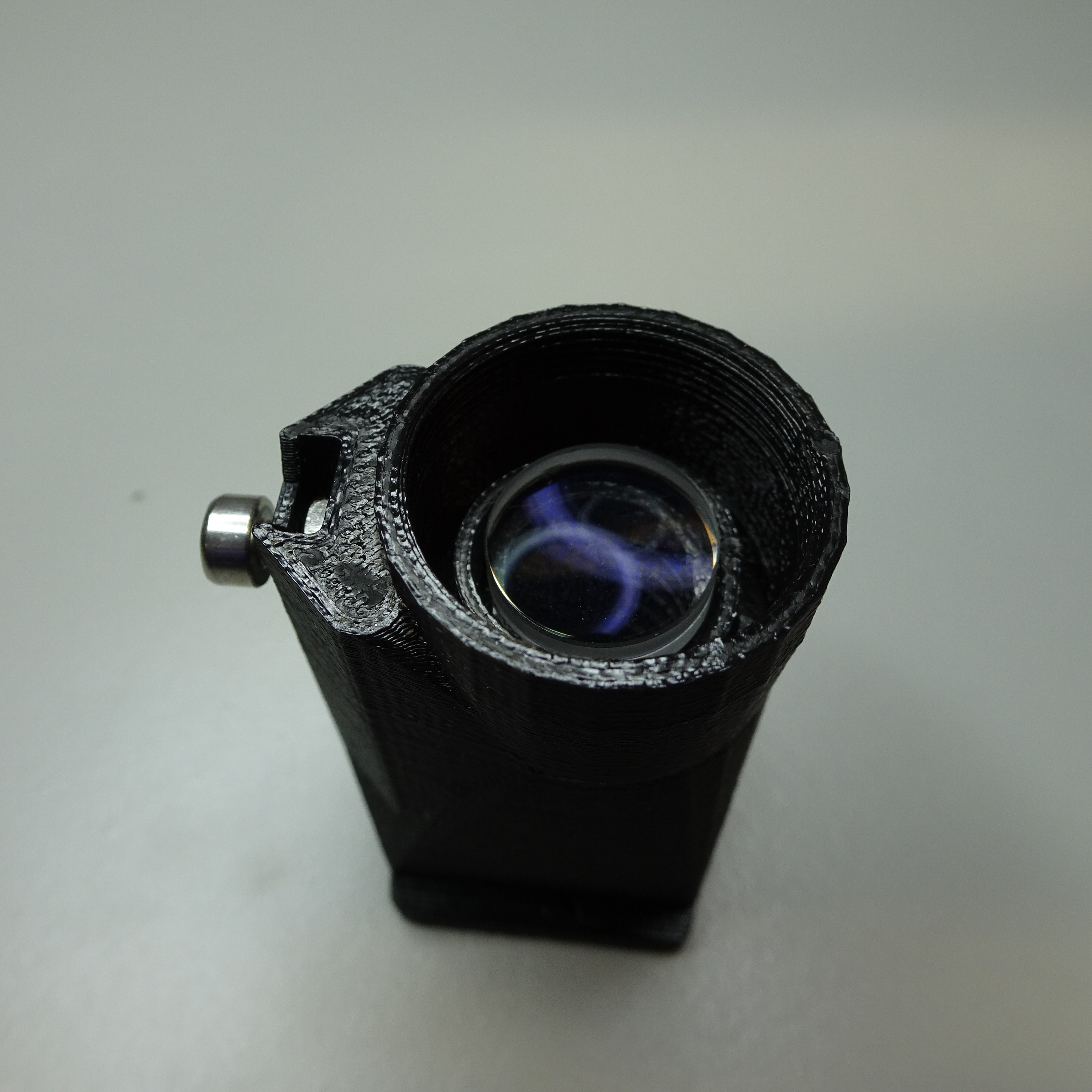
Insert the tube lens
Put the tube lens onto the lens tool, with the more convex side down.
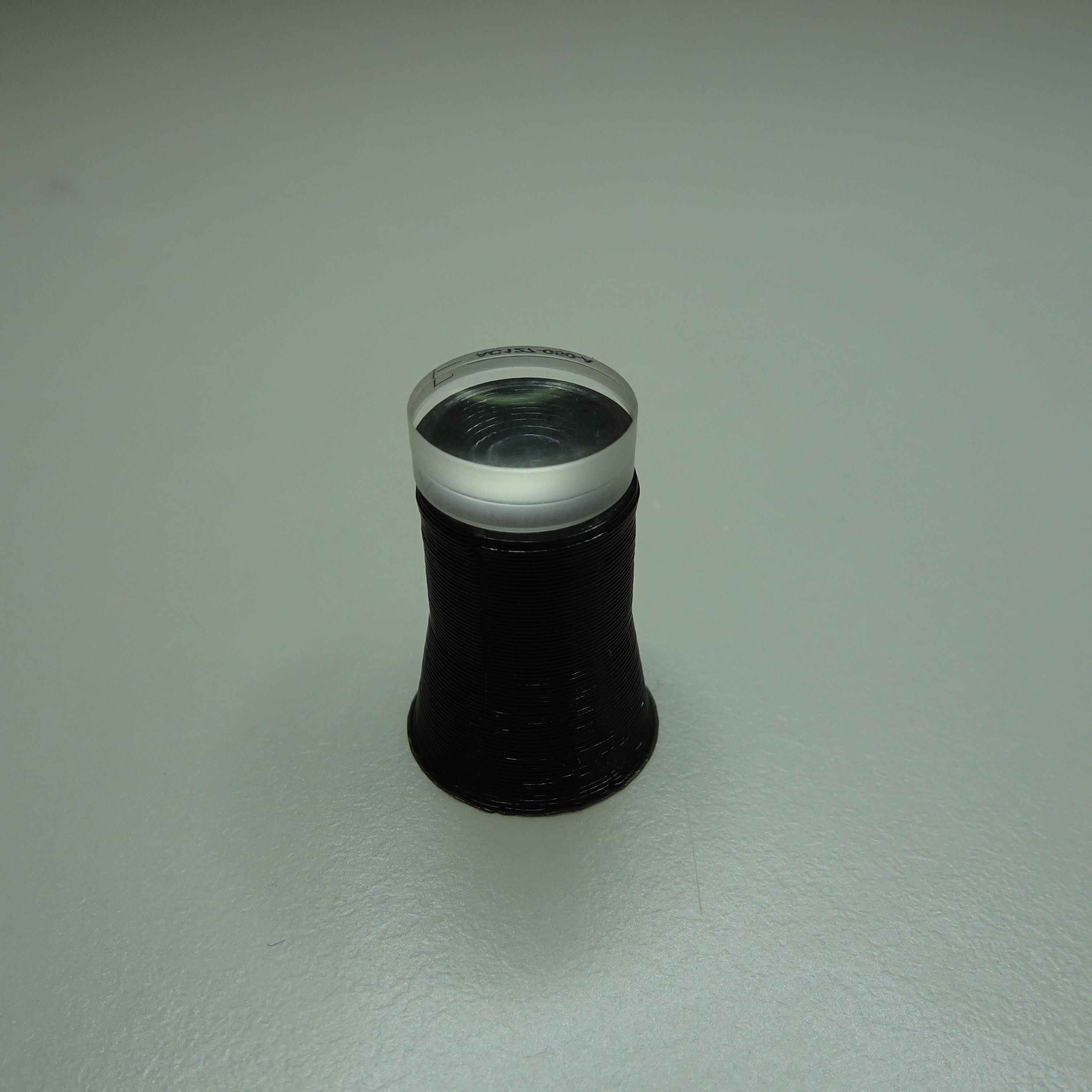
Push the transmission optics module casing down on top of the lens until it is flat and secure.
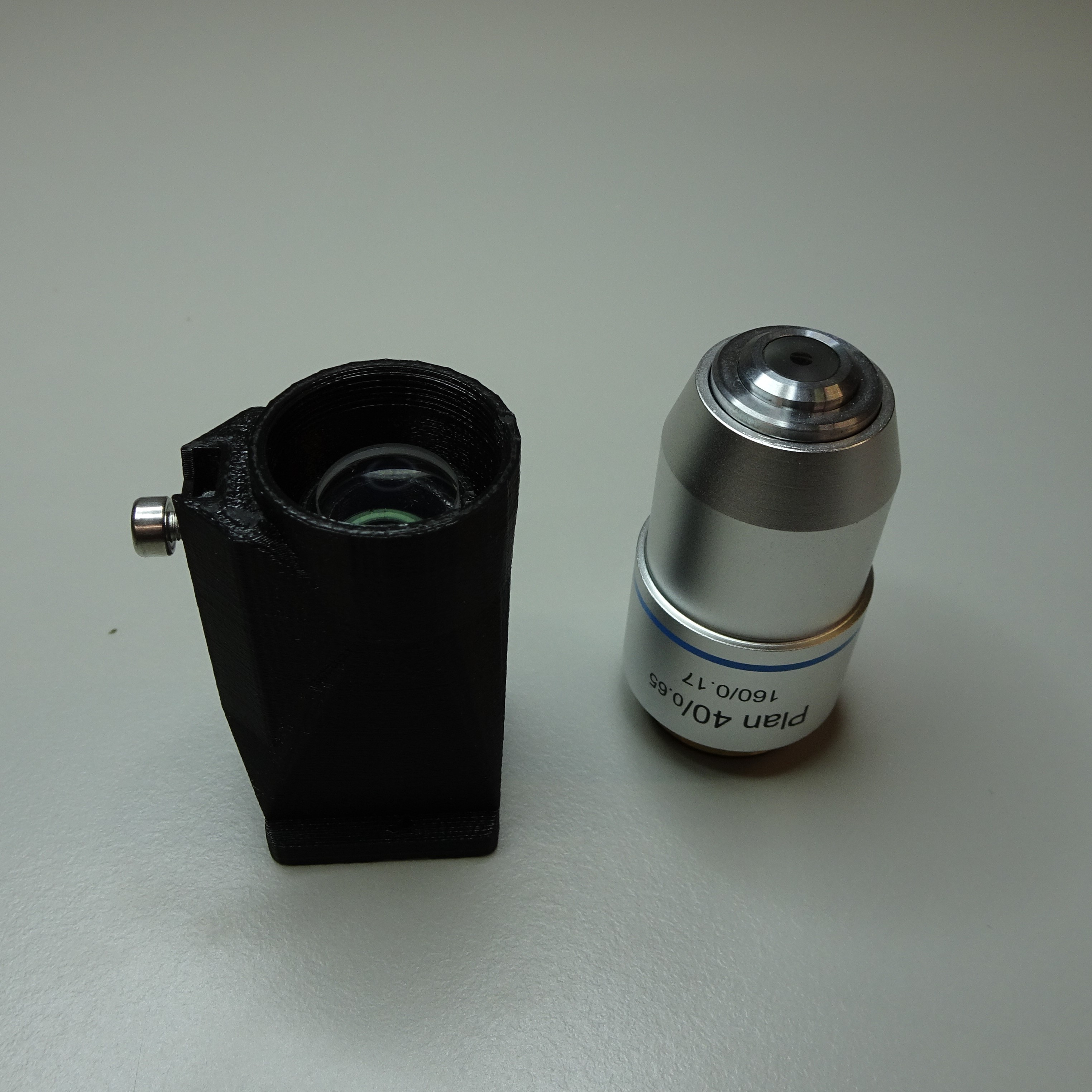
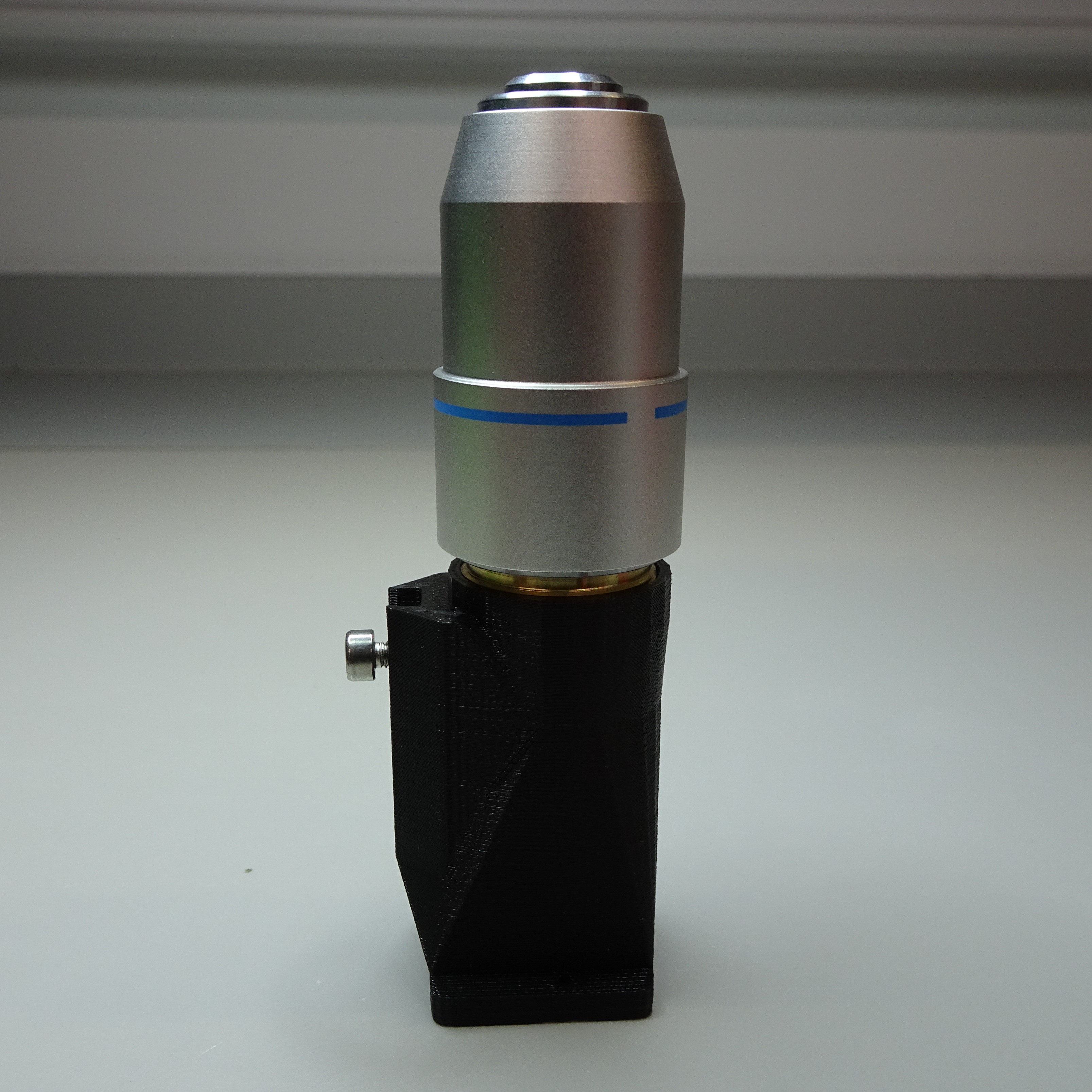
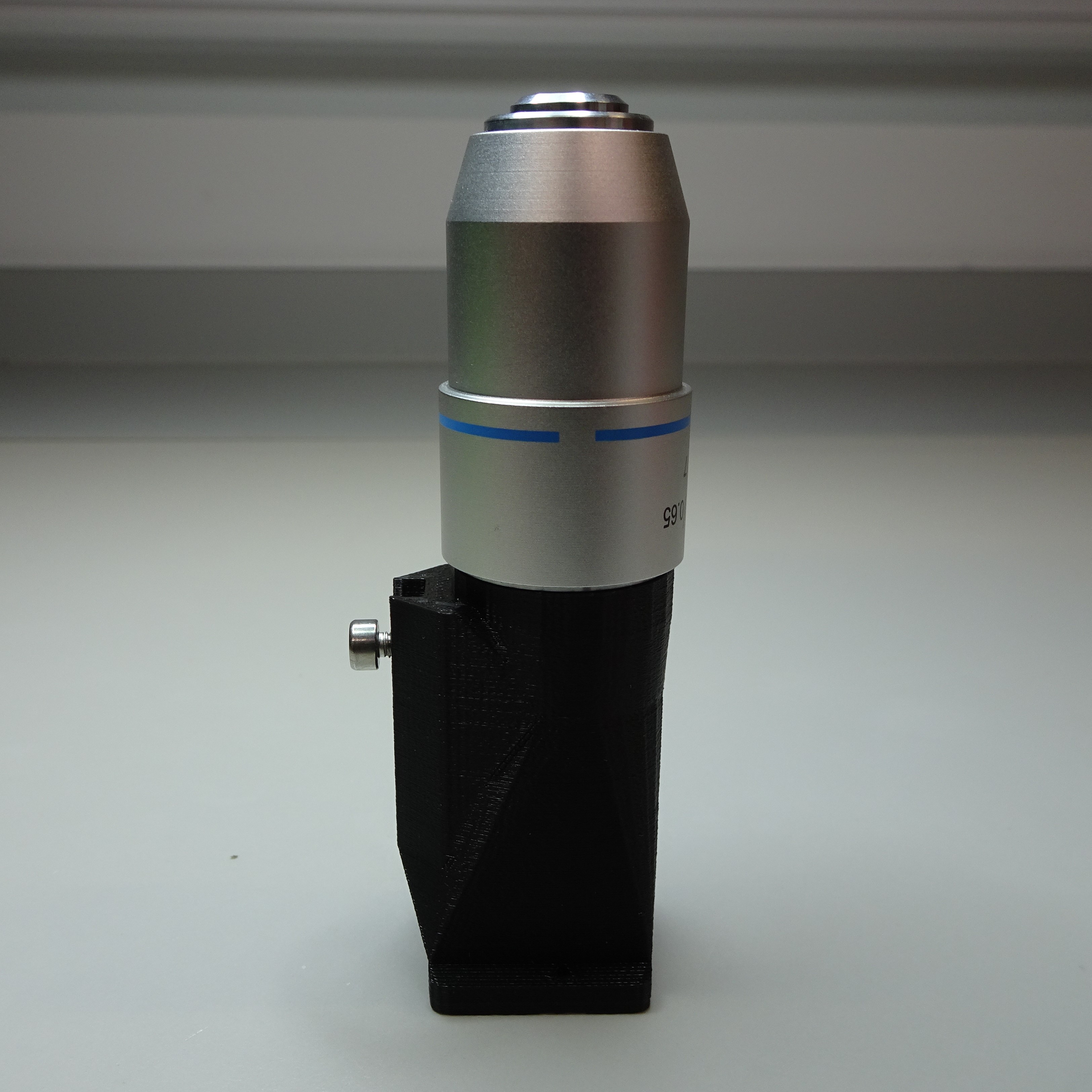
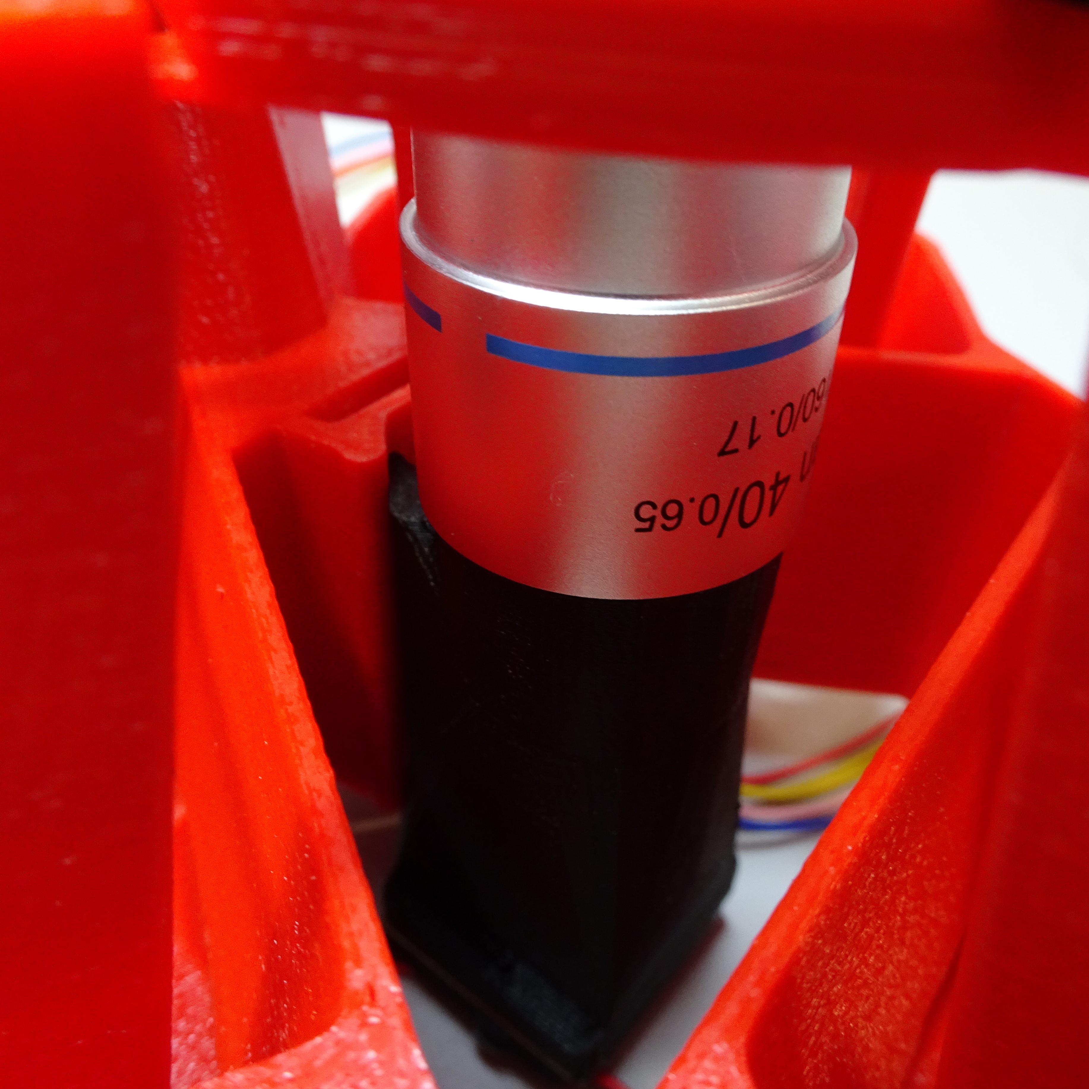
Attach the objective lens
Screw the objective lens into the top of the transmission optics module casing. Be careful to screw it in straight, to avoid cross-threading.
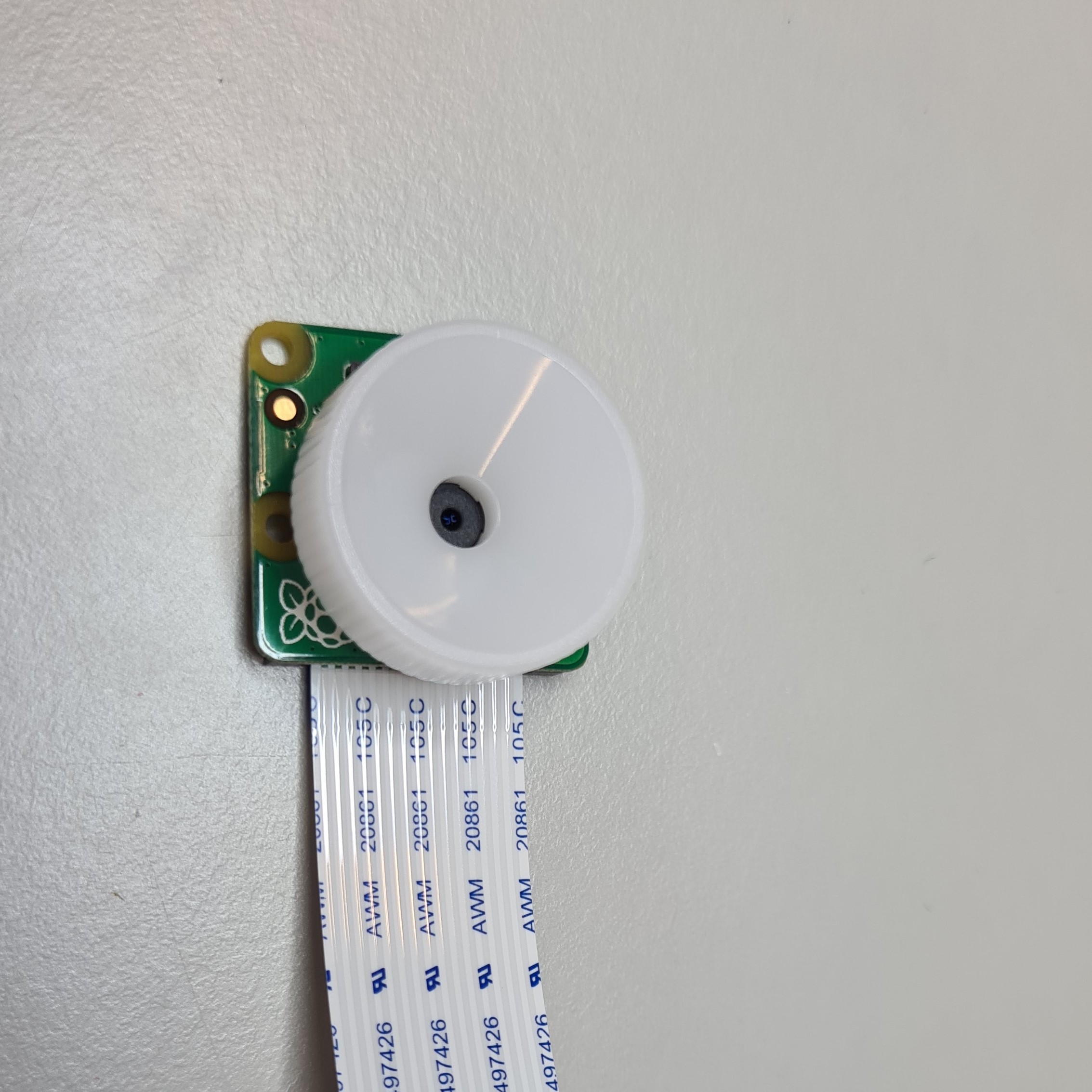
Remove the camera lens
Remove the plastic film from the lens of the Raspberry Pi camera v2.
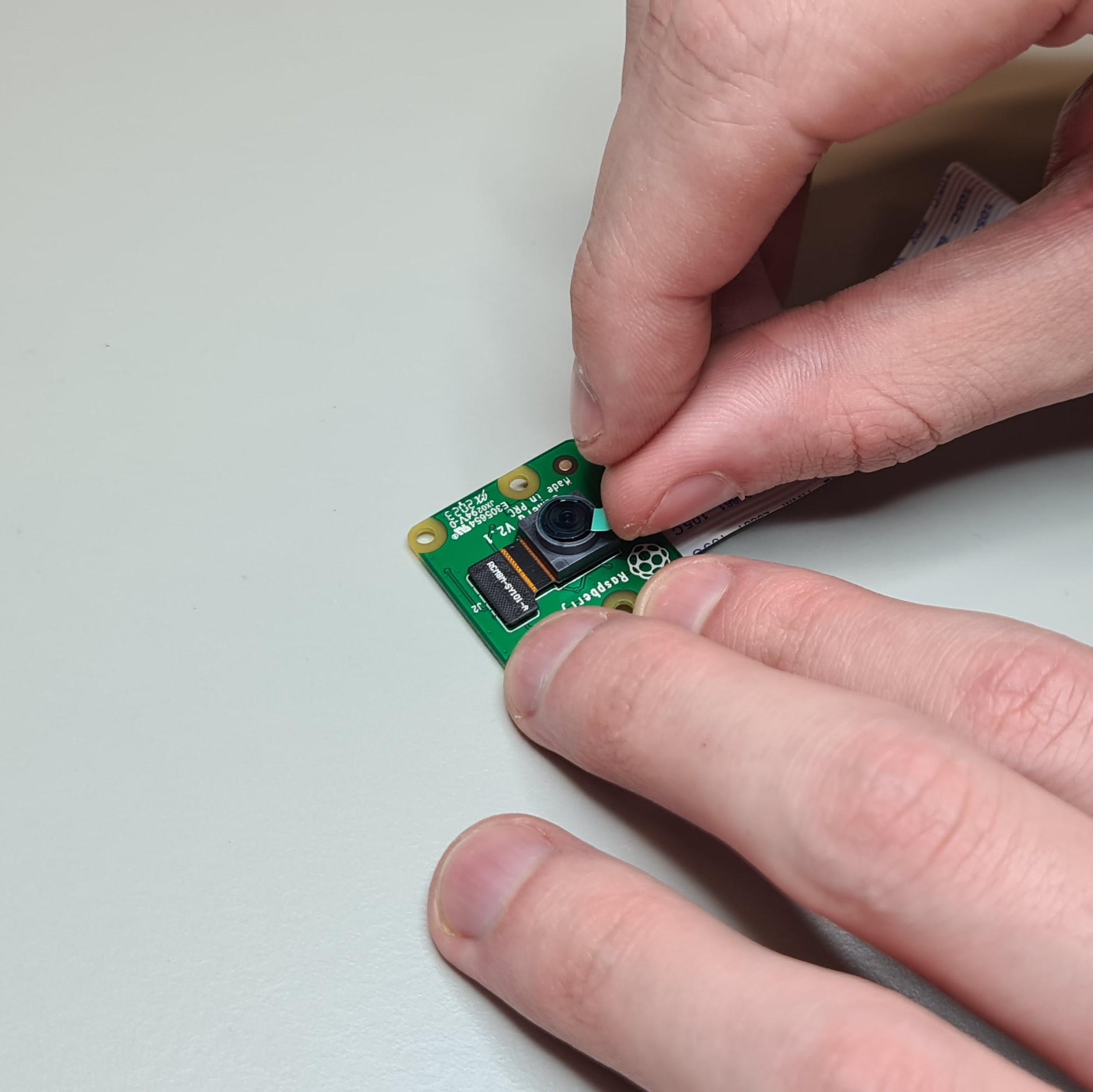
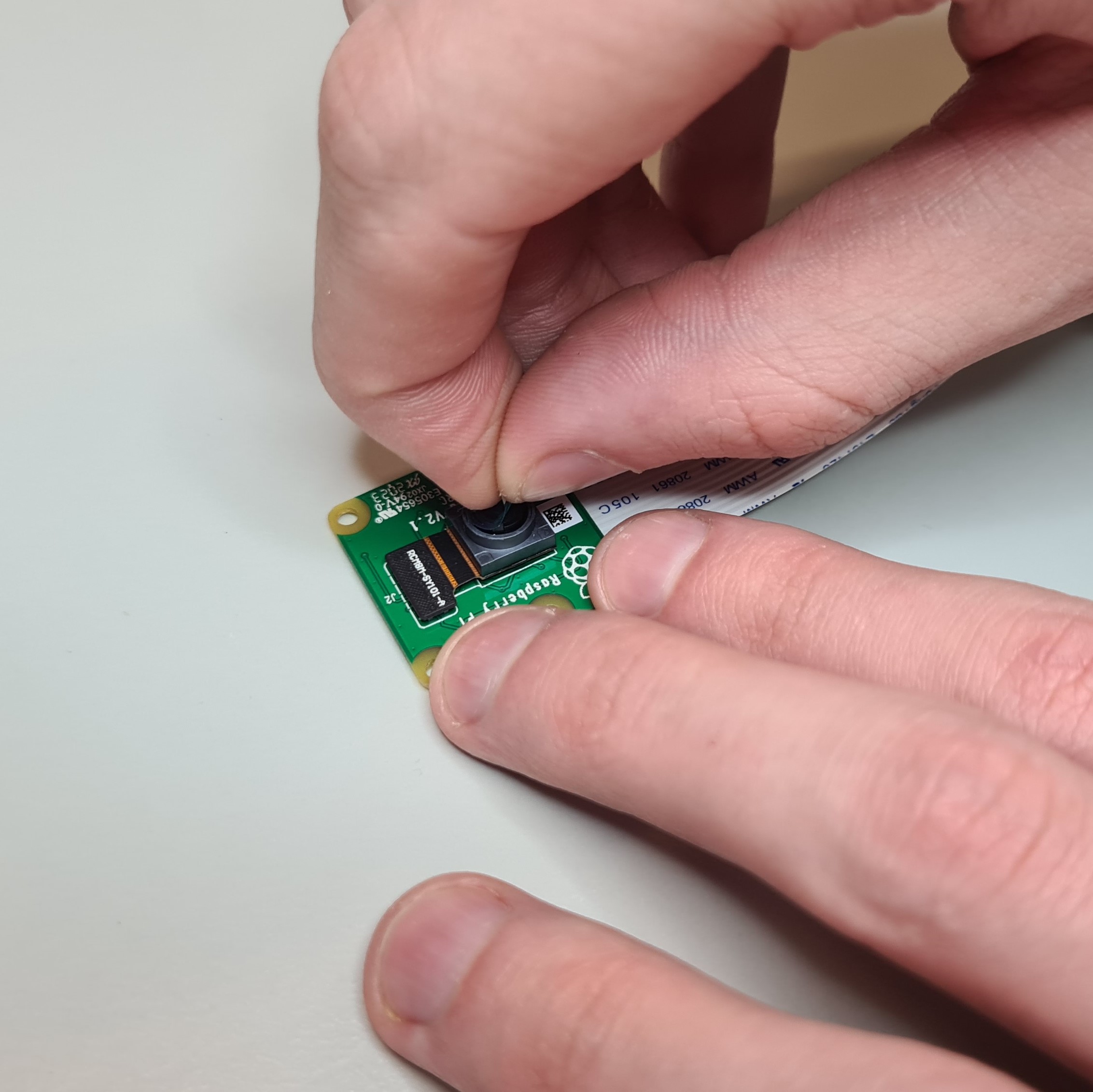
Unscrew the camera lens using the camera lens tool supplied with the camera.
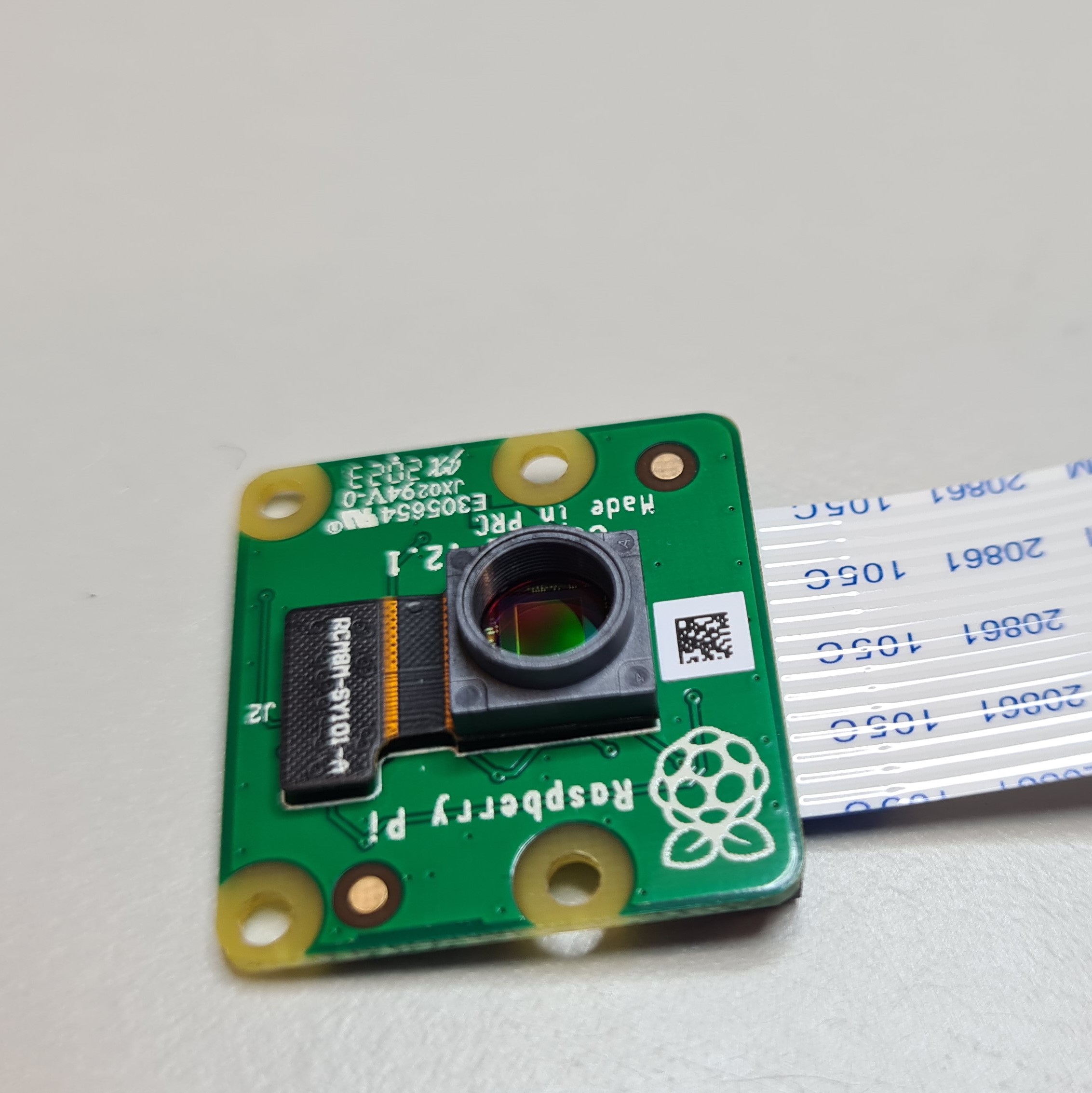
Once you've removed the lens, keep the camera face down or put some tape over the lens holder to stop dust settling on the sensor (which is difficult to clean!).
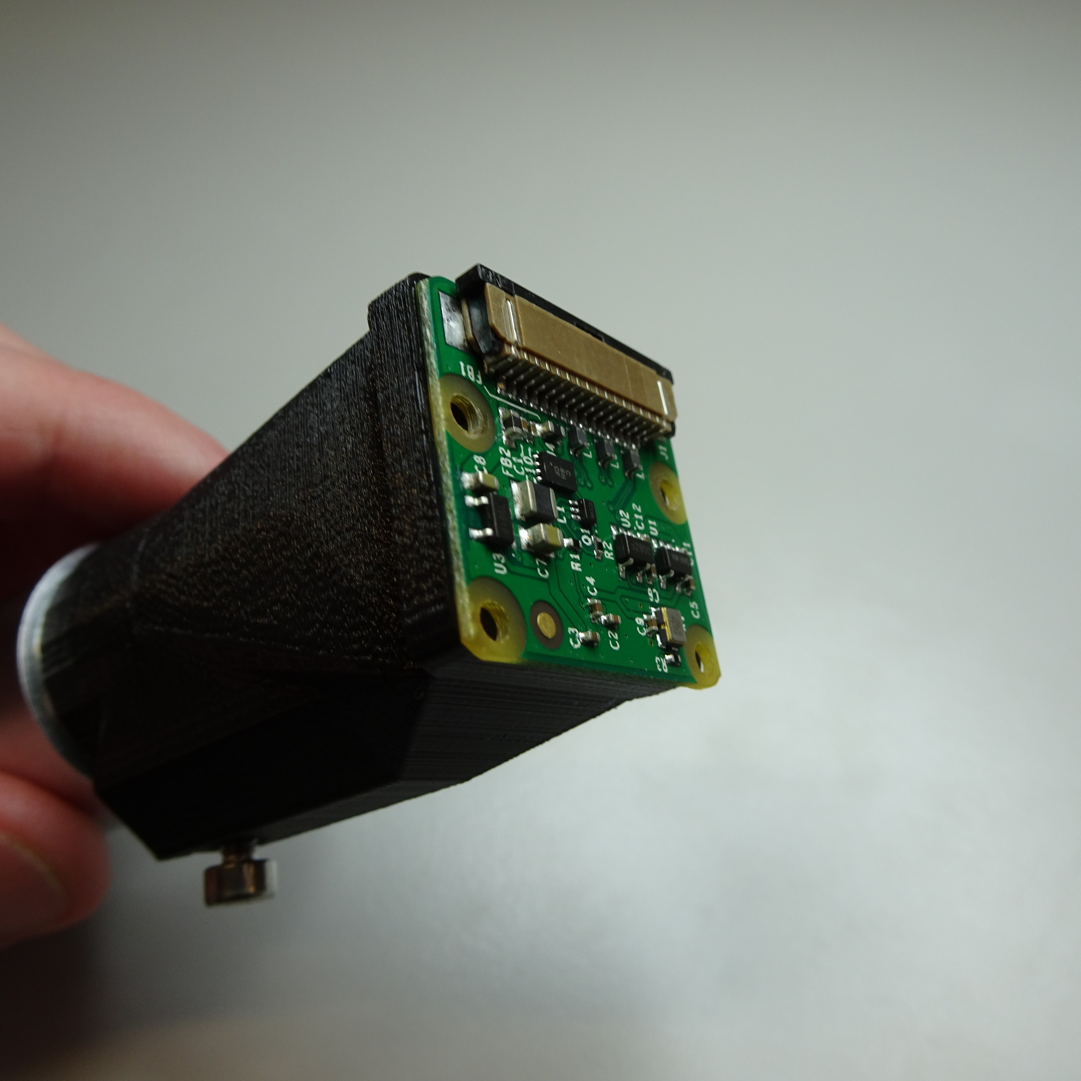
Attach the camera to the optics tube
Attach the Raspberry Pi camera v2 to the bottom of the transmission optics module casing. Put the camera cover over the top. Secure everything in place with two M2x6mm screws.
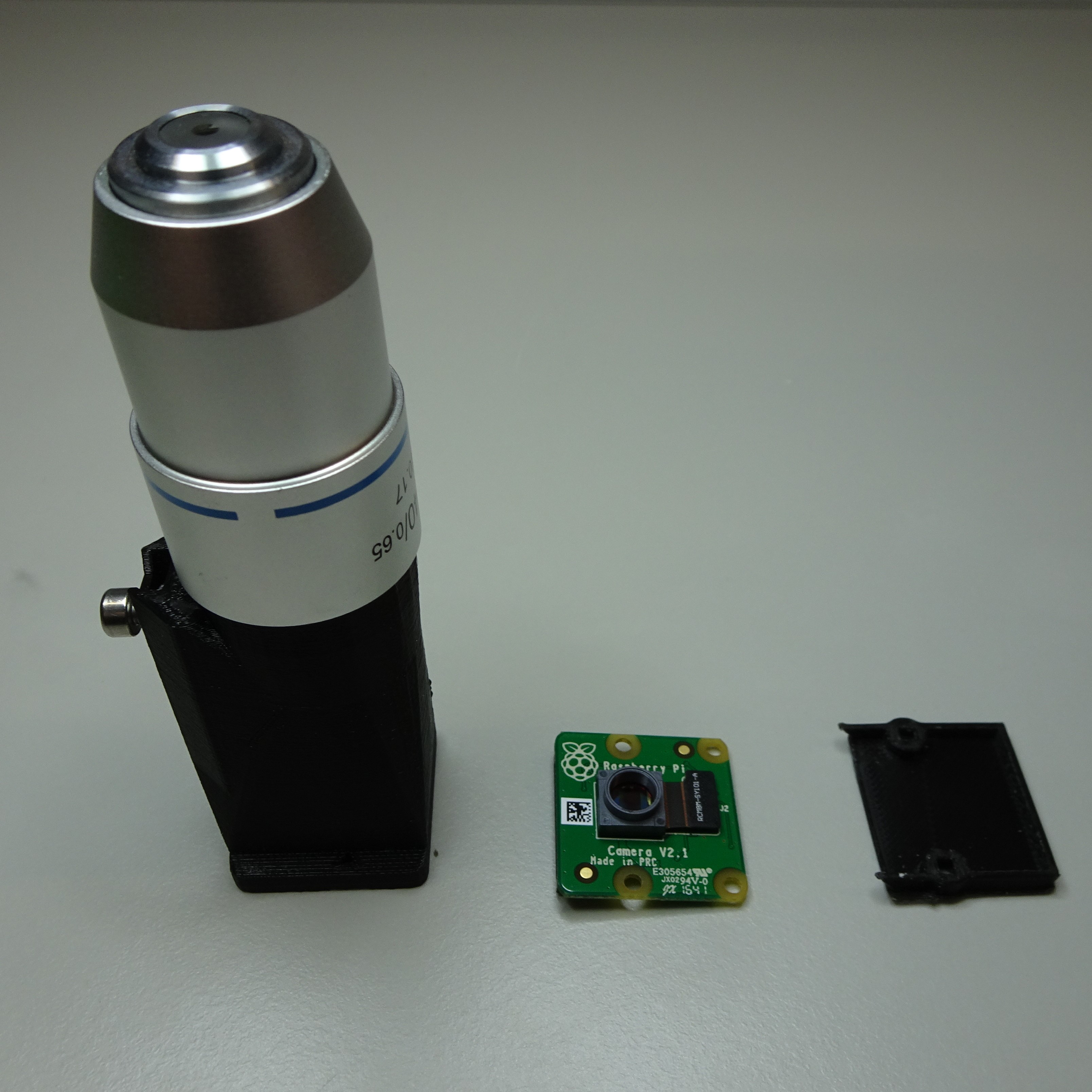
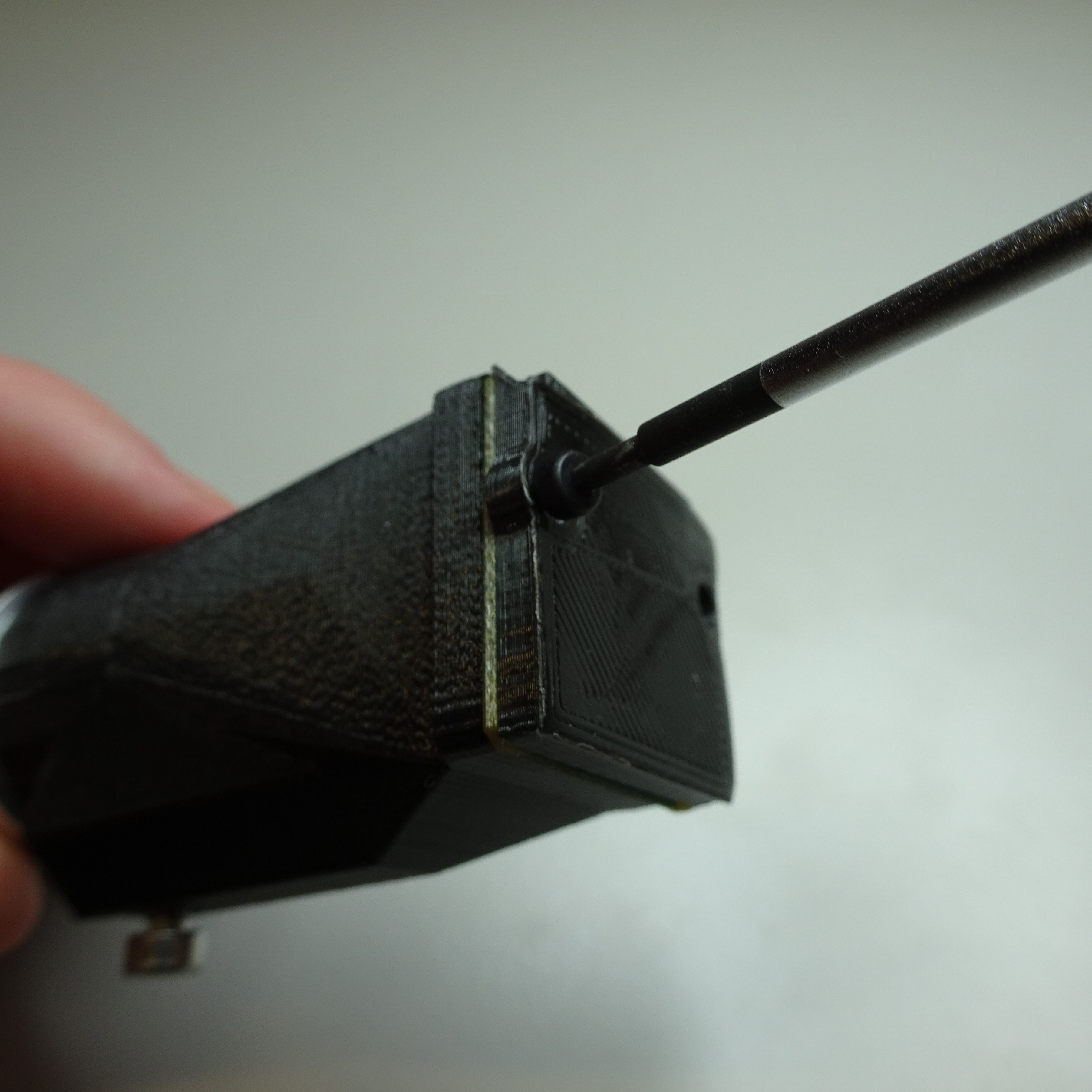
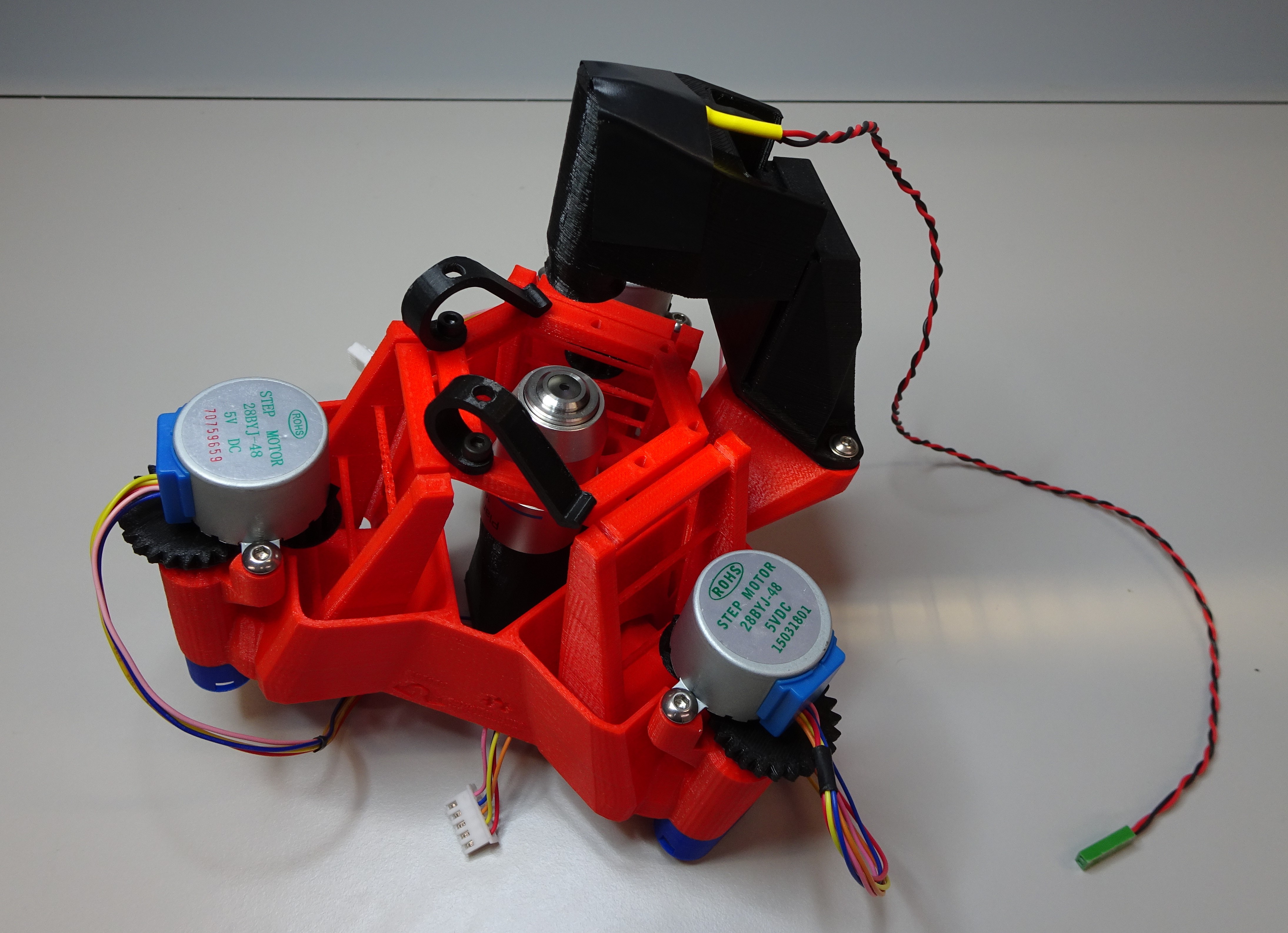
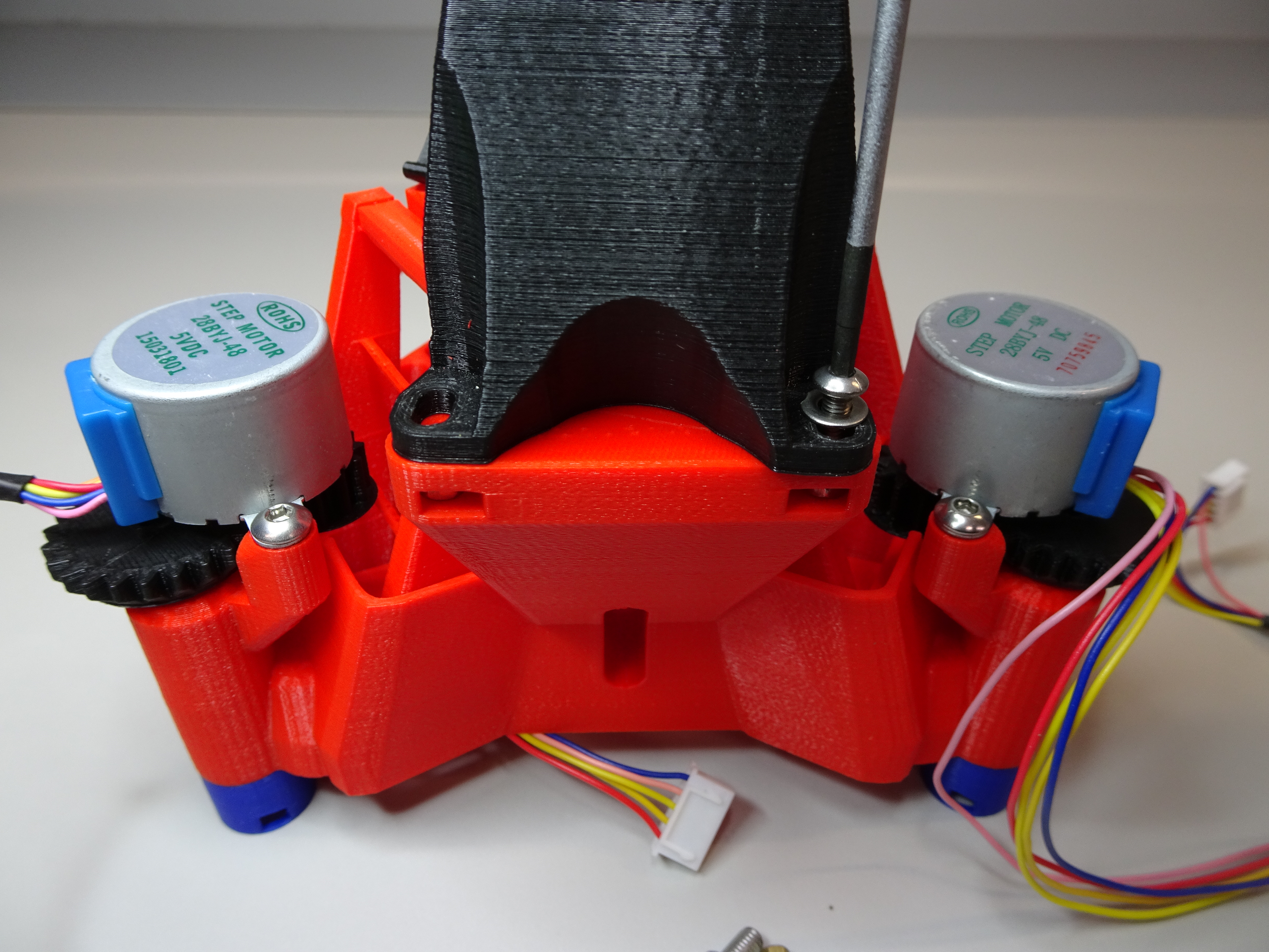
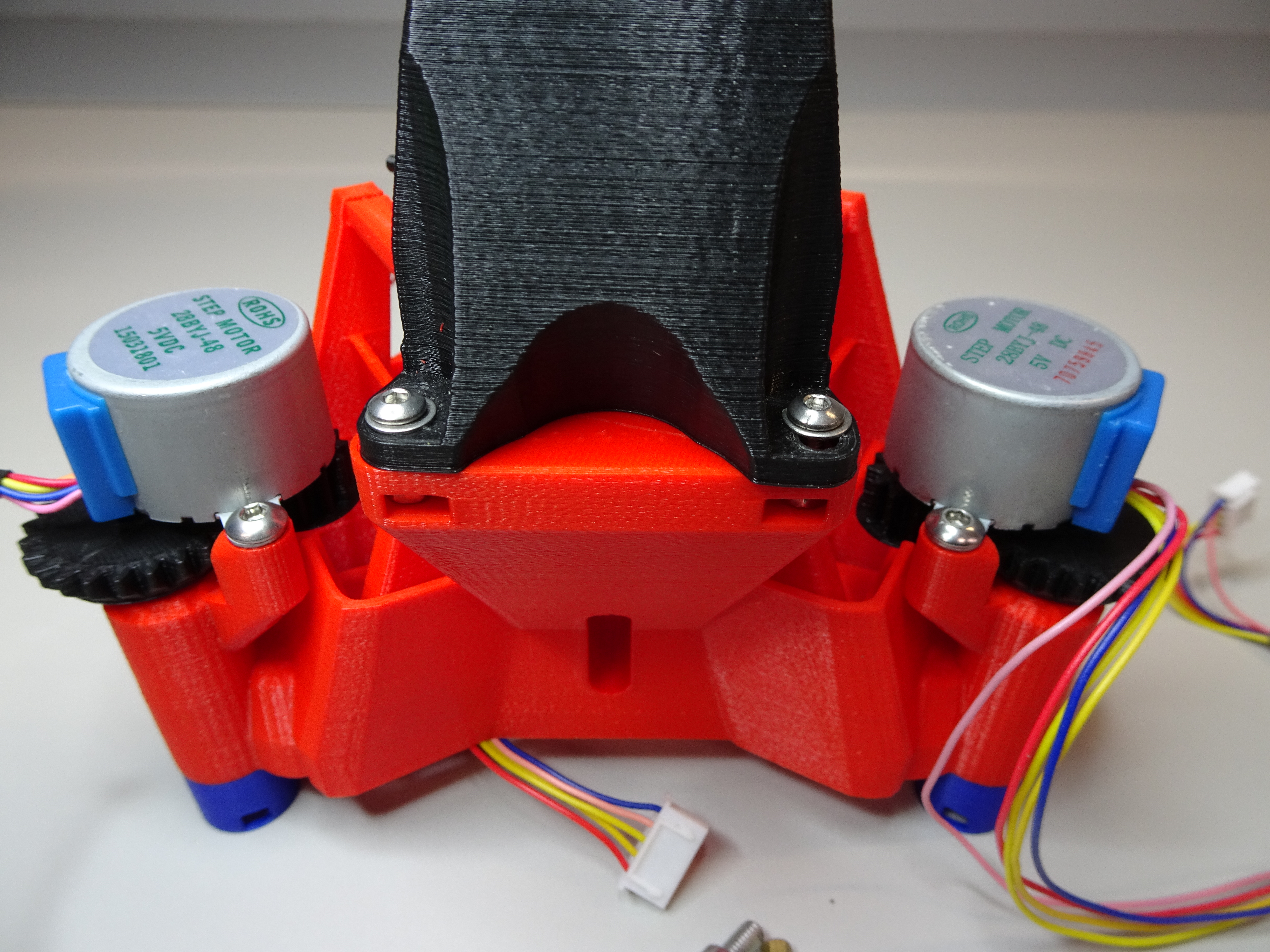
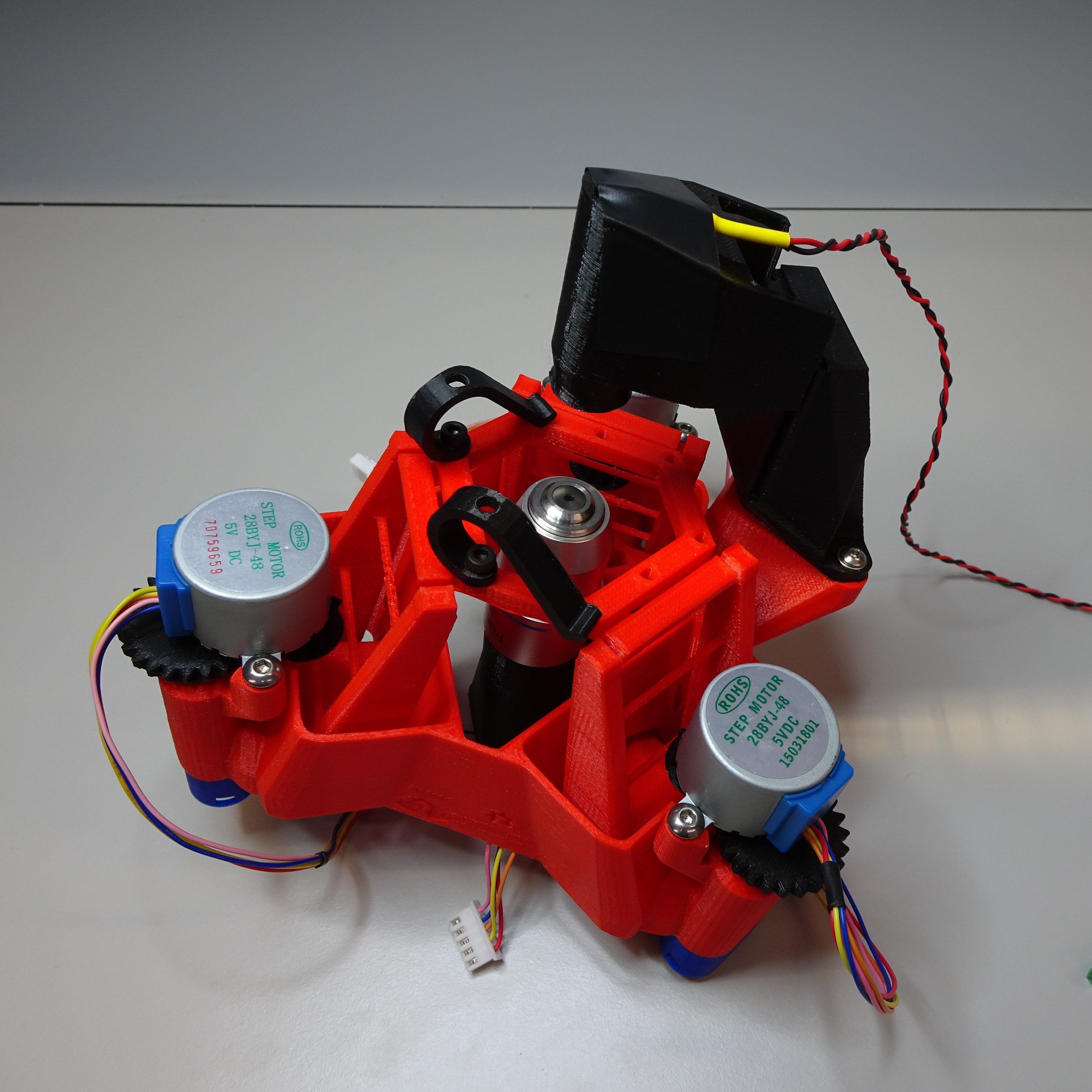
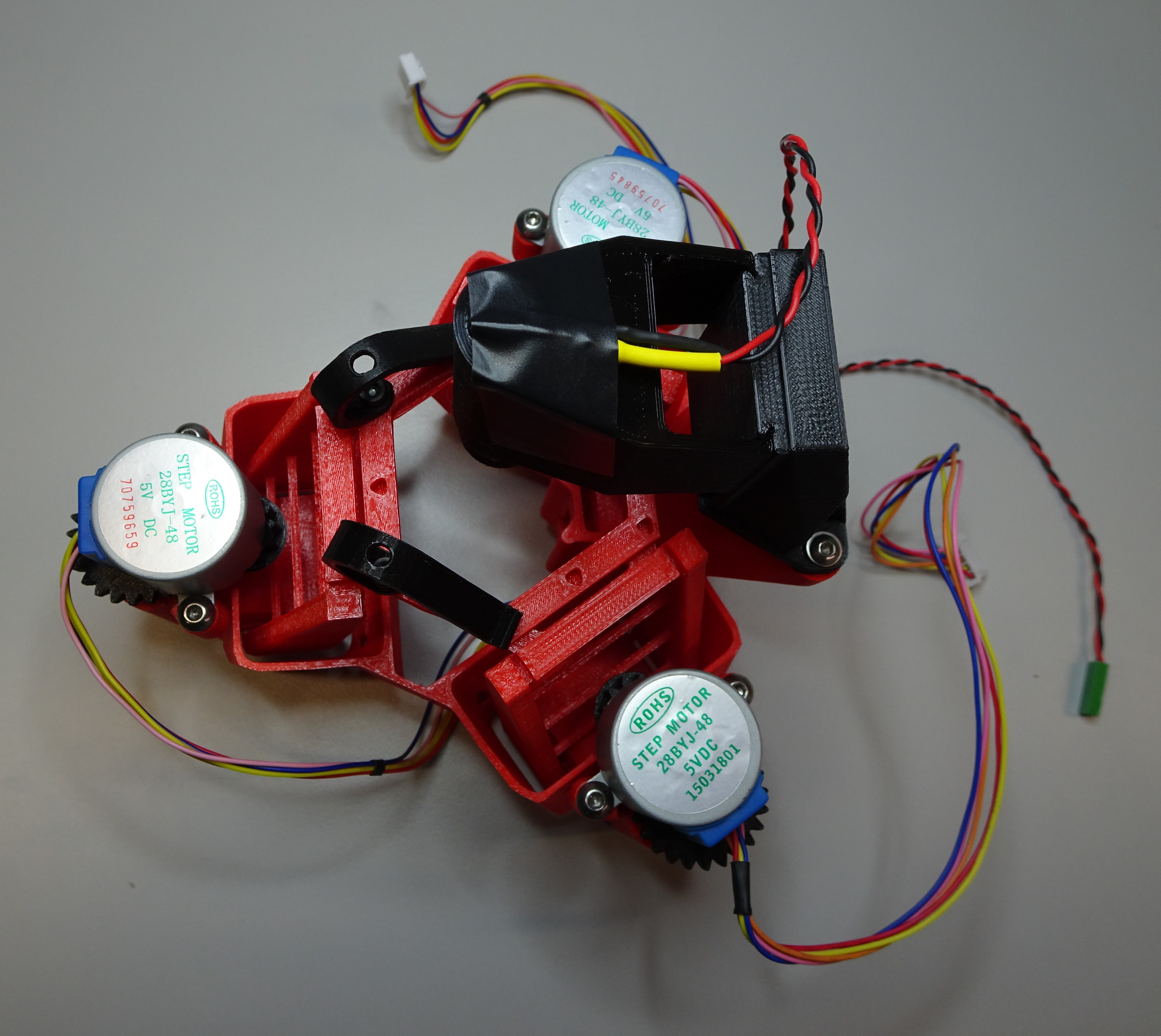
Attach the optics module to the Delta Stage
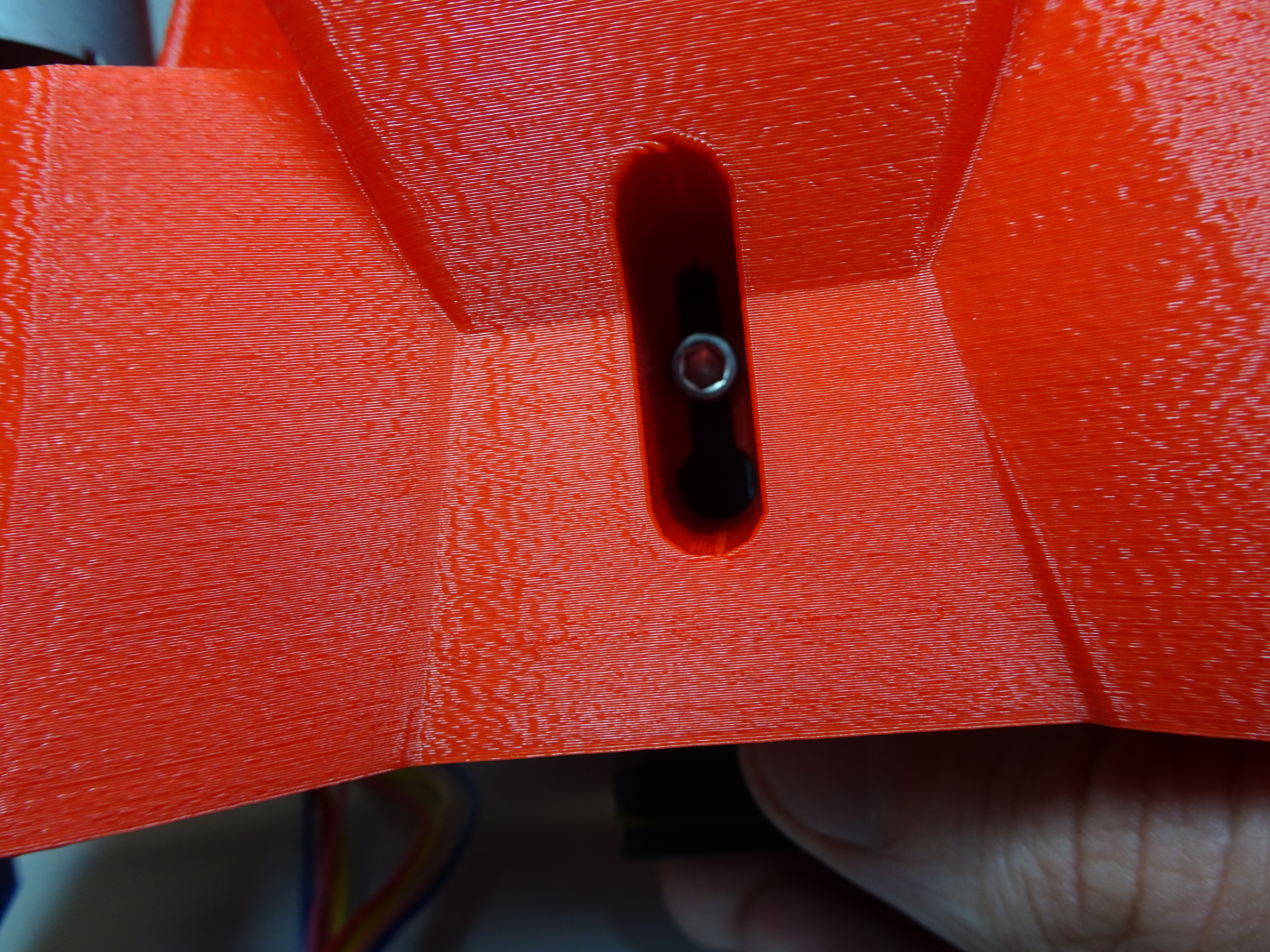
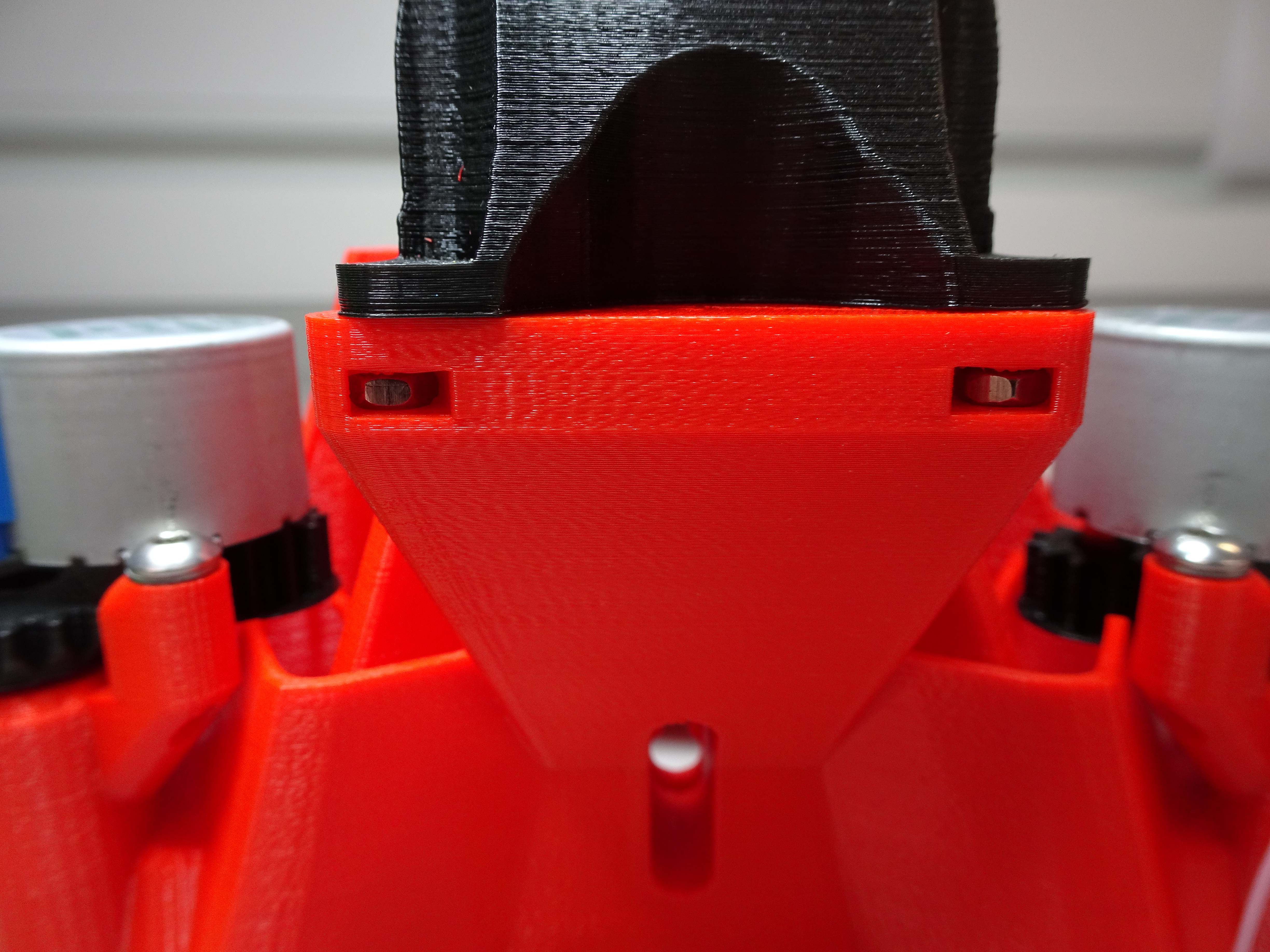
Slot the objective screw into the mount inside the main body.
When the optics module is in roughly the correct position, the objective screw can be tightened through the access hole in the back.